
Installation Manual

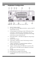
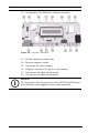
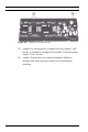
Table Of Contents
- 1 Important Information
- 2 Safety Instructions
- 3 Introduction
- 4 Technical Data
- 5 Installing
- 5.1 Mounting
- 5.2 Unmounting
- 5.3 Opening the Case
- 5.4 Closing the Case
- 5.5 Cabling
- 5.6 Grounding and Shielding
- 5.7 Connecting Power Supply
- 5.8 Ethernet Interface
- 5.9 RS-485 Host Interface
- 5.10 RS-232 Host Interface
- 5.11 DIL switch selector
- 5.12 RS-485 for extension modules
- 5.13 Wiegand Interface for Card Readers
- 5.14 Connecting Relay Outputs
- 5.15 Connecting Analog Input Devices
- 5.16 Tamper Protection
- 6 Operating
- 7 Appendix

AMC2 4W Introduction | en 15
Bosch Sicherheitssysteme GmbH Installation manual | V 7.6 | 2008.12
12. Configurable 10/100 Mbit/s Ethernet interface
Figure 3.4 Overview - Interfaces
13. RS-485 extension module bus
14. External tamper contact
15. Connector for power supply
16. Wiegand interfaces for up to 4 card readers
17. Connectors for eight analog inputs
18. Connectors for eight relay outputs
i
NOTICE!
All connectors, with the exception of the RS232 and Ethernet
host interface, are pluggable screw clamp terminals.