
Installation Manual

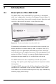
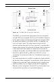
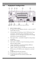
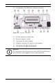
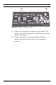
Table Of Contents
- 1 Important Information
- 2 Safety Instructions
- 3 Introduction
- 4 Technical Data
- 5 Installing
- 5.1 Mounting
- 5.2 Unmounting
- 5.3 Opening the Case
- 5.4 Closing the Case
- 5.5 Cabling
- 5.6 Grounding and Shielding
- 5.7 Connecting Power Supply
- 5.8 Ethernet Interface
- 5.9 RS-485 Host Interface
- 5.10 RS-232 Host Interface
- 5.11 DIL switch selector
- 5.12 RS-485 for extension modules
- 5.13 Wiegand Interface for Card Readers
- 5.14 Connecting Relay Outputs
- 5.15 Connecting Analog Input Devices
- 5.16 Tamper Protection
- 6 Operating
- 7 Appendix

14 en | Introduction AMC2 4W
| V 7.6 | 2008.12 Installation manual Bosch Sicherheitssysteme GmbH
3.2 Equipment Configuration
Figure 3.3 Upper circuit board with display (top side)
1. Internal tamper contact
2. DIL switch for RS-485 address selection, protocol and RS-
232/RS-485 selection
3. Lithium battery for buffering of static RAM and real time
clock (RTC). The battery life is estimated at 10 years,
nevertheless an error message is generated if the voltage
sinks below a preset minimum level.
4. Reset push button - reachable through the casing using a
screwdriver
5. Liquid Crystal Display
6. Push button, available on top of the housing, to select
different display modes.
7. Jumper: Equalization of potential between different
systems and earth ground (shield)
8. Jumper: Interface selector RS-485 Host connection, RS-
485 two wire or RS-485 four wire (depends on external
wiring)
9. Configurable RS-485 host interface
10. Docking port for compact flash memory
11. Configurable RS-232 host interface (ribbon cable
connector)