
Installation Manual

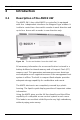
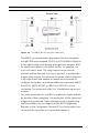
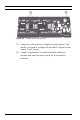
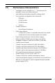
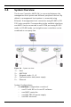
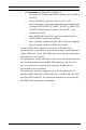
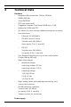
Table Of Contents
- 1 Important Information
- 2 Safety Instructions
- 3 Introduction
- 4 Technical Data
- 5 Installing
- 5.1 Mounting
- 5.2 Unmounting
- 5.3 Opening the Case
- 5.4 Closing the Case
- 5.5 Cabling
- 5.6 Grounding and Shielding
- 5.7 Connecting Power Supply
- 5.8 Ethernet Interface
- 5.9 RS-485 Host Interface
- 5.10 RS-232 Host Interface
- 5.11 DIL switch selector
- 5.12 RS-485 for extension modules
- 5.13 Wiegand Interface for Card Readers
- 5.14 Connecting Relay Outputs
- 5.15 Connecting Analog Input Devices
- 5.16 Tamper Protection
- 6 Operating
- 7 Appendix

AMC2 4W Introduction | en 13
Bosch Sicherheitssysteme GmbH Installation manual | V 7.6 | 2008.12
Figure 3.2 The AMC2 4W in a four door safety lock
The AMC2 can communicate upstream to the host computer
using RS-485 multi-dropped, RS-232 or 10/100 Mbit/s Ethernet.
It has eight analog input devices and eight relay outputs. With
its analog input devices, the AMC2 verifies, for example, if a
lock is closed or open. The relay outputs can be used to
activate lock mechanisms if access is granted, or activate the
burglar alarm system if an intrusion or system alert is detected.
If the eight inputs and outputs on board are not enough to
configure the system, up to three additional extensions (AMC2
8I-8O-EXT, AMC2 16I-EXT, or AMC2 16I-16O-EXT) can be
connected. The extensions offer 8 or 16 additional inputs and
outputs.
The setup procedure for an AMC2 is made very simple and fast
by the use of door templates. Once selected, all the inputs and
outputs are predefined. These settings can be changed using
the Device Editor (Access Engine) of the BIS Configuration
Browser or the Configurator (Access PE) to choose every free
contact of the controller or a connected extension.