AMC2 4W APC-AMC2-4WCF en Installation manual
AMC2 4W Table of Contents | en 3 Table of Contents 1 Important Information 5 1.1 Explanation of symbols in this document 5 1.2 Internet 6 2 Safety Instructions 7 2.1 Important Safety Notes 7 2.2 Safety Precautions 2.3 Unpacking 9 3 Introduction 12 3.1 Description of the AMC2 4W 12 3.2 Equipment Configuration 14 3.3 Performance Characteristics 17 3.4 System Overview 18 4 Technical Data 20 5 Installing 23 5.1 Mounting 23 5.2 Unmounting 24 5.
en | Table of Contents AMC2 4W 5.11 DIL switch selector 5.12 RS-485 for extension modules 41 5.13 Wiegand Interface for Card Readers 43 5.13.1 Connecting different reader types 44 5.14 Connecting Relay Outputs 48 5.15 Connecting Analog Input Devices 51 5.16 Tamper Protection 53 6 Operating 54 6.1 Status Display of the AMC2 4W 54 6.2 Configuring the Ethernet Interface 56 6.3 Resetting the AMC2 4W 57 6.3.1 Resetting the Software 57 6.3.
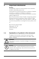
AMC2 4W 1 Important Information | en 5 Important Information Remarks This hardware is part of a security system. Access should be limited to authorized persons only. Some states do not allow the exclusion or limitation of implied warranties, or limitation of liability for incidental or consequential damages, hence the above limitation or exclusion might not apply to you. Bosch Security Systems retains all rights not expressly granted.
en | Important Information 1.2 AMC2 4W Internet If you are interested in further information on this product or information on other products, please consult our website at http://www.boschsecuritysystems.com. | V 7.6 | 2008.
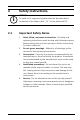
AMC2 4W 2 7 Safety Instructions i 2.1 Safety Instructions | en NOTICE! To build an UL approved system refer the documentation contained in the folder titled "_UL" on the delivered CD. Important Safety Notes 1. Read, follow, and retain instructions - All safety and operating instructions must be read and followed properly before putting the unit into operation. Retain instructions for future reference. 2. Do not ignore warnings - Adhere to all warnings on the unit and in the operating instructions.
en | Safety Instructions 6. AMC2 4W Damage which requires service - Disconnect the unit from the main AC or DC power source and refer servicing to qualified service personnel under the following conditions: – If the power supply cord or plug is damaged. – If liquid has been spilled or an object has fallen into – If the unit has been exposed to water and/or the unit. inclement weather (rain, snow, etc.). – If the unit does not operate normally when following the operating instructions.
AMC2 4W Safety Instructions | en 9 60950. Unsuitable replacements may damage the unit or cause fire or shock. – For units intended to operate at 12V DC normal input voltage is 12V DC. Voltage input must never exceed 15V DC. 10. Lightning - For added protection during electrical storms external lightning conductors can be installed. This prevents power surges from damaging the unit. 11. The units should be installed in locations with restricted access. 2.
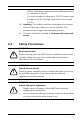
en | Safety Instructions AMC2 4W WARNING! Health and Safety! Installation of the AMC2 device must comply with any local fire, health and safety regulations. A secured door that may be part ! of an escape route from an area must be installed with: – A fail-safe lock (A). So that the door will be released if – A normally-closed break-glass or manual pull (B) in the lock power fails. Ideally, a magnetic lock should be used.
AMC2 4W Safety Instructions | en 11 If any parts are missing, inform your customer service representative or a Bosch Security Systems salesperson. The shipping carton is the safest transport container for the unit. Store it and the other packaging material for future use. If the unit has to be sent back, use the original packaging. Bosch Sicherheitssysteme GmbH Installation manual | V 7.6 | 2008.
en | Introduction AMC2 4W 3 Introduction 3.1 Description of the AMC2 4W The AMC2 4W (also called AMC2 or controller) is equipped with four independent interfaces for Wiegand type readers. It is able to control two doors with a reader in each direction and up to four doors with a reader in one direction only. Figure 3.1 The Access Modular Controller AMC2 4W All necessary information for access verification is stored in a battery buffered on-board memory and a Compact Flash (CF) memory card.
AMC2 4W Introduction | en 13 Figure 3.2 The AMC2 4W in a four door safety lock The AMC2 can communicate upstream to the host computer using RS-485 multi-dropped, RS-232 or 10/100 Mbit/s Ethernet. It has eight analog input devices and eight relay outputs. With its analog input devices, the AMC2 verifies, for example, if a lock is closed or open. The relay outputs can be used to activate lock mechanisms if access is granted, or activate the burglar alarm system if an intrusion or system alert is detected.
en | Introduction 3.2 AMC2 4W Equipment Configuration Figure 3.3 1. 2. Upper circuit board with display (top side) Internal tamper contact DIL switch for RS-485 address selection, protocol and RS232/RS-485 selection 3. Lithium battery for buffering of static RAM and real time clock (RTC). The battery life is estimated at 10 years, nevertheless an error message is generated if the voltage sinks below a preset minimum level. 4.
AMC2 4W Introduction | en 15 12. Configurable 10/100 Mbit/s Ethernet interface Figure 3.4 Overview - Interfaces 13. RS-485 extension module bus 14. External tamper contact 15. Connector for power supply 16. Wiegand interfaces for up to 4 card readers 17. Connectors for eight analog inputs 18. Connectors for eight relay outputs i NOTICE! All connectors, with the exception of the RS232 and Ethernet host interface, are pluggable screw clamp terminals.
en | Introduction Figure 3.5 AMC2 4W Jumper at the bottom side 19. Jumper for setting either voltage free relay output (“dry” mode) or looped-in voltage from the AMC2 internal power supply (“wet” mode). 20. Jumper: Equalization of potential between different systems and earth ground (shield) for the extension interface. | V 7.6 | 2008.
AMC2 4W 3.3 Introduction | en 17 Performance Characteristics – Intelligent access manager for 1 ...
en | Introduction 3.4 AMC2 4W System Overview The Access Controller AMC2 4W is connected between the management host system and different peripheral devices. By default, a management host system is connected using Ethernet. A management host connection using RS-485 or RS232 is also possible. Corresponding to the available interfaces, one AMC2 can be connected to each COM port using RS-232 mode. In RS-485 mode, up to eight access controllers can be combined on one party line. Figure 3.
AMC2 4W Introduction | en – 19 the maximum configuration consists of – up to two PC’s with shared BIS software [Access PE = one PC] – up to 200 AMC2 controller [Access PE = 64] – each controller can be extended with any combination of three AMC2 8I-8O-EXT, AMC2 16I-EXT, or AMC2 16I16O-EXT input/output modules [Access PE = one extension board] – each AMC2 4W controller can be extended with an AMC2 4W-EXT extension module – the necessary number of AMC PBC-60 power supplies – the necessary numbe
4 en | Technical Data AMC2 4W Technical Data Hardware – Integrated Microcontroller (32 bit, 30 MHz) – SRAM (256 kB) – Serial EEPROM – RTC (real time clock) – Pluggable Compact Flash from 64 MB up to 1 GB – Battery for SRAM and RTC – DIL switch for host settings (address and protocol mode) – Host interfaces – Ethernet 10/100 Mbit/s – RS-485 2-wire or 4-wire Transfer rate: 38,4 kBit/s (even parity, 7 bit, 1 stop bit) – RS-232 Transfer rate: 38,4 kBit/s (no parity, 8 bit, 1 stop bit)
AMC2 4W Technical Data | en 21 10 to 30 Vdc Display 64,8 mm x 13,9 mm (2.551 x 0.547 in.) 1 line, 16 characters Power consumption AMC: 5 VA Peripheral devices: using the PBC-60 – up to 55 VA – constant load: 25 VA Connectors Pluggable screw connectors Protection class IP30 Environment temperature 0° C to 45° C (32° F to 113° F) Humidity Up to 95%, without condensation Housing material ABS with OC (UL 94 V-0) Dimensions (W/H/D) 232mm x 90mm x 63mm (8.9 x 3.5 x 2.4 in.) Weight app. 0,53 kg (0.
en | Technical Data i AMC2 4W NOTICE! Using several devices in an installation system take care about the greatest minimum and the lowest maximum value for the environment. Take these for the system limits. | V 7.6 | 2008.
AMC2 4W 5 23 Installing i 5.1 Installing | en NOTICE! To build an UL approved system refer the documentation contained in the folder titled "_UL" on the delivered CD. Mounting The AMC2 can be attached on a standard 35 mm (1.377 in.) mounting rail using a snap-in mechanism. Attach the AMC2 into the upper edge of the mounting rail [1], then push down the device and snap it onto the rail by pushing it towards the back [2]. Figure 5.
en | Installing 5.2 AMC2 4W Unmounting i NOTICE! To remove the AMC2 from a mounting rail, first, remove all pluggable connectors. Push down the AMC2 until the lower edge snaps out of the mounting rail [1]. Pull the lower end of the AMC2 from the mounting rail [2]. Figure 5.2 | V 7.6 | 2008.
AMC2 4W 5.3 Installing | en 25 Opening the Case i NOTICE! To open the AMC2, first remove all pluggable connectors. The AMC2 case consists of a top cover mounted with a twopoint snap-in closure on a chassis. To open the case, push down the two snap-ins with a screwdriver, then swing the cover down. Figure 5.3 Opening the AMC2 case Bosch Sicherheitssysteme GmbH Installation manual | V 7.6 | 2008.
en | Installing 5.4 AMC2 4W Closing the Case Before aligning the covers, unplug any pluggable screw connectors. Insert the hooks on the lower edge of the front cover into the lugs on lower edge of the plastic back cover [1]. Please ensure that the BOSCH logo is not upside-down. The upper edge of the front cover now aligns with the two-point snap-in closures on the upper edge of the back cover [2], and may thus be clicked gently into place.
AMC2 4W 5.5 Installing | en 27 Cabling WARNING! The cables used in the AMC2 access control system are not ! prone to electrical interference. However, you should avoid routing cables close to heavy load switching cables and equipment. If this is unavoidable, cross the cable at right angles every 1 to 2 m (3 to 6 ft) to reduce interference. 5.5.1 Conductor data With the calculation below you can find out which cable type must be used.
en | Installing AMC2 4W NOTICE! i These specifications apply to power supply, readers, relay outputs, and extension interface. Regarding inputs, specific voltage-drop values need to be taken into account. Refer to Table 5.3 5.6 Grounding and Shielding The main grounding point at the AMC2 is connected to pin 2 of the power supply connector - see Table 7.3. It is good practice to shield all wires carrying low level signals.
AMC2 4W 5.6.1 Installing | en 29 Host Interface Figure 5.5 Location of ground jumper RS-485 host interface The jumper setting A1 shows the factory settings. Jumper JP1 connects the internal ground of the AMC2 4W to the ground of the RS-485 host interface. Jumper JP2 manages the signal ground. Settings for jumper JP1: If the ground conductor and the shield on the host are not connected and ...
en | Installing i 5.6.2 AMC2 4W NOTICE! If the AMC2 is set to RS-232 mode, set jumper JP1 (= A2). Extension Interface Figure 5.6 Location of ground jumper bottom side Jumper B connects the internal ground of the AMC2 to the RS485 ground of the slave interface. Only set jumper B (B2) if the AMC2 powers all other peripheral devices directly connected to it. | V 7.6 | 2008.
AMC2 4W 5.7 Installing | en 31 Connecting Power Supply Connect the power supply to the POWER 7-pin pluggable screw connector on the upper case. Refer to Table 7.3 for a complete diagram. Figure 5.7 Location of the power supply connector Connect an external power supply (10 - 30 Vdc) for the AMC2 device at pin 1 (positive) and pin 3 (negative) of the pluggable screw connector.
en | Installing 5.8 AMC2 4W Ethernet Interface The AMC2 offers a 10/100 Mbit/s Ethernet auto-sensing interface to connect to a local area network or host computer. i NOTICE! Use either a CAT5 crossover cable to connect the AMC2 directly to host computer, or a standard CAT5 patch cable to connect the AMC2 via a network. A complete connection diagram of the Ethernet host interface is shown in Table 7.2. Figure 5.
AMC2 4W 5.9 Installing | en 33 RS-485 Host Interface An RS-485 host system can consist of up to eight AMC2 controllers connected using 2- or 4-wire connection. Figure 5.
en | Installing – AMC2 4W Peripheral devices are AMC2 which are connected to the host computer. – Maximum cable length of a bus line must not exceed 1200 m (4000ft). – The cable length of branch lines must not exceed 100m (330ft). – Any bus line conductor connects up to eight AMC2. Do not exceed the maximum number of devices. – For longer bus lines connect the AMC2 to multiple AMCMUX (-EXT) with the host. NOTICE! Up to seven AMC-MUX-EXT can be connected to an AMC-MUX.
AMC2 4W Installing | en Figure 5.10 5.9.1 35 RS-485 host interface RS-485 Two Wire Connection Figure 5.11 1= 2= 3= 4= Connection scheme of a RS-485 two wire connection signal ground TxRx+ TxRxshield Bosch Sicherheitssysteme GmbH Installation manual | V 7.6 | 2008.
en | Installing AMC2 4W Figure 5.12 Settings for RS-485 two wire connections For RS-485 two wire connection, set the AMC-MUX DIL switch at positions 3, 7 and 8 to ON. On the upper side of the AMC panel, put the jumper on the two pins on the right hand side of connector 8. Also refer to Figure 3.3. Set the RS-485 address of the AMC2 controller using the DIL switch. Refer to Section 5.11 DIL switch selector. 5.9.2 RS-485 Four Wire Connection Figure 5.13 1= 2= | V 7.6 | 2008.
AMC2 4W Installing | en 3= 4= 5= 6= 37 TxRxsignal ground Tx+ Tx- Figure 5.14 Settings for RS-485 four wire connection For RS-485 four wire connection, set the AMC-MUX DIL switch at positions 3, 5 and 6 to ON. On the upper side of the AMC panel, put the jumper on the two pins on the right hand side of the connector 8. Also refer to Figure 3.3. Set the RS-485 address of the AMC2 controller using the DIL switch. Refer to Section 5.11 DIL switch selector.
en | Installing 5.10 AMC2 4W RS-232 Host Interface The AMC2 offers an RS-232 serial interface to connect a host computer or serial modem. ! WARNING! Cable length between two RS-232 COM serial interfaces must not exceed 15 meters (45 ft). Figure 5.15 Location of the RS-232 serial interface As the AMC2 controller is conceptionally a PC, it is not possible to connect them directly using normal cables. Use instead a null modem or “crossover” cable.
AMC2 4W 5.11 Installing | en 39 DIL switch selector DIL switches are used to configure the host settings. The first four DIL switches for address selection define the RS-485 address of the AMC2 in a RS-485 bus system. Switch 5 selects one of the two different protocols, SDEB and BPA (according to DIN6619). Switch 6 sets the connection to the host system to either RS-232 or RS-485. NOTICE! If using an Ethernet connection, set switch 1 to ON (= factory i setting).
en | Installing AMC2 4W DIL Switches Address 1 2 3 4 none OFF OFF OFF OFF 1 ON OFF OFF OFF 2 OFF ON OFF OFF 3 ON ON OFF OFF 4 OFF OFF ON OFF 5 ON OFF ON OFF 6 OFF ON ON OFF 7 ON ON ON OFF 8 OFF OFF OFF ON Table 5.1 Setting the address via the DIL switch DIL Switches Mode 5 6 ON SDEB RS-232 OFF BPA RS-485 Table 5.2 Protocol and connection settings | V 7.6 | 2008.
AMC2 4W 5.12 Installing | en 41 RS-485 for extension modules The RS-485 Extension Module Bus expands the AMC2 4W with additional I/O modules (AMC2 8I-8O-EXT, AMC2 16I-16O-EXT, or AMC2 16I-EXT) and/or with the reader interface extension AMC2 4W-EXT. Figure 5.17 Location of the RS-485 extension module bus Up to three expansion modules can be connected to provide additional in- and outputs, for example, for elevator control.
en | Installing Figure 5.18 | V 7.6 | 2008.
AMC2 4W 5.13 Installing | en 43 Wiegand Interface for Card Readers The AMC2 4W provides four ports for connecting a maximum of 4 readers with Wiegand interfaces. Each interface is connected using a 10-pin pluggable screw connector (S2, S7, S14, and S19) - refer to Figure 7.3. Figure 5.19 Location of the Wiegand interfaces for external devices These interfaces are point-to-point connections, and each can support only a single reader with a maximum cable length of 150m (492 ft).
en | Installing 5.13.1 AMC2 4W Connecting different reader types Connection schemes and reader wiring colors vary from type to type, and so may differ from the 10-pole Wiegand to AMC connection shown in the appendix (Table 7.4) i NOTICE! If your reader requires a voltage other than 12V then it will require an external power supply. Wiegand reader type W 1 This wiring diagram refers to the following readers from the BOSCH catalog: | V 7.6 | 2008.12 CTN Part Number ARD-ProxPointPlus 4.998.141.
AMC2 4W Installing | en 45 NOTICE! The terminal assignment shown above does not apply to the W1 i readers ARD-R90-AKT00 (F.01U.030.232) and ARD-R90 (F.01U.027.003). Please use instead the installation guide of the card reader itself. The Wiegand reader interface of the the AMC2 4W does not provide sufficient power for the ARD-R90. Please plan an external power supply for the ARD-R90.
en | Installing i AMC2 4W NOTICE! The beeper will be controlled by the reader. Wiegand reader type W 3 This wiring diagram refers to the following readers from the BOSCH catalog: | V 7.6 | 2008.12 CTN Part Number ARD-AYK12 F.01U.075.408 ARD-AYJ12 F.01U.075.388 ARD-AYH12 F.01U.075.389 ARD-AYQ12 F.01U.075.390 ARD-AYCE65B F.01U.075.
AMC2 4W Installing | en 47 Wiegand reader type W 4 1 green LED 2 red LED 3 Data 0 4 Data 1 5 - 6 Reader Supply - 0V 7 Reader Supply: 8 - 30VDC 8 - 9 - 10 - The reader has an additional DIL switch to choose the following parameter settings. S1 = on S2 = on The beeper is controlled by input 1. The beeper will allways be set after card reading. S3 = on The LED displays will be controlled by the reader. i S4 = off S5 = on The beeper is controlled by input 2.
en | Installing 5.14 AMC2 4W Connecting Relay Outputs To operate locks or alarm systems, the AMC2 has eight form C relay outputs. The outputs will be connected to the 3-pin pluggable screw connectors: S5, S6, S10, S11, S17, S18, S22, and S23 - refer to Table 7.6. Figure 5.20 Location of the relay output connectors Each relay output can operate in ‘wet’ mode, using the AMC2's internal 12Vdc power supply for external devices or ‘dry’ mode with potential free contacts for externally powered systems.
AMC2 4W Installing | en Figure 5.21 ! 49 Wet mode and dry mode of the AMC2 relay outputs WARNING! Please note the following specifications. To prevent damage to the relays please remember: – the maximum switching current is 1.25 A – the maximum switching voltage is 30 Vdc – only ohm resistive load can be connected to the relay – inductive loads have to be short circuited using recovery diodes - refer to Figure 5.22. These diodes (1N4004) are supplied with every AMC2 package.
en | Installing AMC2 4W Figure 5.22 Recovery diode schematic 1 normally open/ 2 3 4 normally closed common load diode 1 normally open/ 2 3 4 5 normally closed common load diode voltage source WARNING! ! Risk of Damage! Do not connect externally powered devices in wet mode. This can damage the AMC2. Each relay output has a separate jumper setting on the underside of the circuit board to select wet (D 2) or dry (D 1) mode. Figure 5.23 | V 7.6 | 2008.
AMC2 4W i 5.15 Installing | en 51 NOTICE! The positions of the jumpers 1 and 2 are interchanged related to the corresponded interfaces. Connecting Analog Input Devices The AMC2 has eight analog inputs, for example, for potentialfree lock mechanisms, or to detect whether a lock is closed or open. The inputs will be connected to the 2-pin pluggable screw connectors: S3, S4, S8, S9, S15, S16, S20, and S21 refer to Table 7.5. WARNING! Risk of damaging equipment.
en | Installing AMC2 4W The AMC2 can also detect the wiring conditions ‘short circuit’ and ‘broken’, and hence trigger an alarm if the appropriate devices are connected. 1. Door open: RS + RP 2. Door closed: RS 3. Open wire: RS + RP = ∞ 4. Short circuit: RS + RP = 0 The resistor values can vary and depend on the used lock system. The extension package includes 2,2 kΩ resistors which can be used to replace RS and RP resistor.
AMC2 4W i 5.16 Installing | en 53 NOTICE! We recommend using serial resistors (RS) no higher than 5K6 in order to obtain clear measurements. Tamper Protection To protect the AMC2 against unauthorized access and so prevent tampering with sensitive data, the AMC2 provides an additional interface to connect external tamper contacts. This interface is a potential-free 2-pin pluggable screw connector marked with T. When not in use this tamper contact should be shorted. Figure 5.
en | Operating AMC2 4W 6 Operating 6.1 Status Display of the AMC2 4W The liquid crystal display delivers status information about the AMC2. Push the 'Dialog' button to switch between different modes. Figure 6.1 Location of the ’Dialog’ button The selected display mode remains set until the next time the button is pressed. The order of the display pages is shown in the following table. Push Display (Example) Description 0 V01.00 02.03.
AMC2 4W Operating | en 55 Push Display (Example) Description 3 Dig. IO: :::::::::::::::: Display of the digital contacts: the input signals set will be shown with an extension above - output signals with an extension below. 3a Dig. I1: :::::::::::::::: If there are I/O-Boards 3b Dig. I2: :::::::::::::::: connected the signals will be 3c Dig. I3: :::::::::::::::: shown on separate pages.
en | Operating 6.2 AMC2 4W Configuring the Ethernet Interface To configure the AMC2 in a TCP/IP network environment, use the AmcIpConfig tool provided in the following directory on the standalone or the remote server of the Building Integration System: \\Runtime-drive:\MgtS\AccessEngine\AC\bin The access control system Access Personal Edition has an entry of this tool in its program folder: Start > Programs > Access Personal Edition > AmcIpConfig This tool can be copied and used on every computer on
AMC2 4W 6.3 Operating | en 57 Resetting the AMC2 4W If problems occur, they should first be tackled directly - for example check the Network connection, IP-address and DIL switch settings. Nevertheless it is sometimes an indirect help to reset the AMC2 unit to its factory defaults. 6.3.1 Resetting the Software 1. Insert the provided screwdriver into the hole until it reaches the reset button as shown in Figure 6.2. 2. 3. Press the reset button for at least three seconds.
en | Operating 6.3.2 AMC2 4W Resetting the Network Configuration 1. Reset the AMC2 as described above. 2. Open the upper case of the AMC2 as described in Section 5.3 Opening the Case. 3. Set all six DIL switches of the RS-485 selector to ON as shown in Figure 6.3. 4. Press the tamper switch on the upper left side of the board. 5. Set the DIL switches back in the address state before resetting. The AMC2 now has the following network configuration: – DHCP = 1 – IP = 0.0.0.
AMC2 4W 7 Appendix | en 59 Appendix Figure 7.1 Connectors on upper PCB 1 Shield 2 Data RxTx+ 3 Data RxTx- 4 Ground (PAG) 5 Data Tx+ 6 Data Tx- Table 7.1 RS-485 host on upper PCB 1 TXD+ 2 TXD- 3 RXD+ 4 not connected 5 not connected 6 RXD- 7 not connected 8 not connected Table 7.2 Ethernet Network socket (RJ45) Bosch Sicherheitssysteme GmbH Installation manual | V 7.6 | 2008.
en | Appendix Figure 7.2 | V 7.6 | 2008.
AMC2 4W Appendix | en 61 Figure 7.3 Connector blocks of the AMC2 4W Bosch Sicherheitssysteme GmbH Installation manual | V 7.6 | 2008.
en | Appendix AMC2 4W 1 Power supply, DC positive (10V - 30V) 2 Shield 3 Power supply (0V) 4 UPS (power good signal) - AC 5 UPS (power good signal) - Battery 6 UPS (power good signal) - DC 7 UPS (power good signal) - Common Table 7.3 Power supply 1 Reader Supply - 12V+ 2 Reader Supply - 0V 3 Data 0 4 Data 1 5 Shield 6 green LED 7 red LED 8 Beeper 9 Hold 10 Card Present Table 7.4 Wiegand interface 1 Analog Input, in 2 Analog Input, out Table 7.
AMC2 4W Appendix | en 1 Power supply for external devices - 12V 2 Power supply for external devices - 0V 3 Shield 4 Data RxTx+ 5 Data RxTx- 6 Ground (PAG) 63 Table 7.7 Extension interface 1 Tamper Contact, in 2 Tamper Contact, out Table 7.8 External tamper contact Bosch Sicherheitssysteme GmbH Installation manual | V 7.6 | 2008.
en | Index AMC2 4W Index C R cabling 27 characteristics 17 contact 6 reader interfaces 15, 17, 20, 43 Wiegand 43 resetting 57 resistor 51 RS-232 host interface 14, 17, 38 RS-485 host interface 14, 17, 33 four wire 37 two wire 36 D description 12 DIL 14, 17, 39 display 54 E S equipment 14 Ethenet host interface 15 Ethernet host interface 17 Ethernet interface 32 extension interface 20, 30 extension interfade 41 Safety notes 9 shielding 28 system overview 18 T G tamper 53 transfer rates 17,
Bosch Sicherheitssysteme GmbH Robert-Koch-Straße 100 D-85521 Ottobrunn Germany Telefon +49 89 6290-0 Fax +49 89 6290-1020 www.boschsecurity.