Microwave Installation Manual 300 SERIES HMV3053U, HMV3063U, HMV3023U
Table of Contents onaiurstlIc Safety Definitions .......................................................... 2 IMPORTANT SAFETY INSTRUCTIONS ........................ 3 Appliance Handling Safety ................................................. 3 Safety Codes and Standards ............................................. 3 Electric Safety ....................................................................... 3 Microwave Safety .................................................................
9 S N I Y T E F A S IMPORTANT SAFETY INSTRUCTIONS READ AND SAVE THESE INSTRUCTIONS INSTALLER: LEAVE THESE INSTRUCTIONS WITH THE APPLIANCE AFTER INSTALLATION IS COMPLETE. T N A T R OD PA ME RI D N A IMPORTANT: SAVE THESE INSTRUCTIONS FOR THE LOCAL ELECTRICAL INSPECTOR'S USE. WARNING If the information in this manual is not followed exactly, fire or shock may result causing property damage or personal injury.
9 IMPORTANT SAFETY INSTRUCTIONS READ AND SAVE THESE INSTRUCTIONS GROUNDING INSTRUCTIONS This appliance must be grounded. Grounding reduces the risk of electric shock by providing a safe pathway for electric current in the event of a short circuit. This appliance is equipped with a cord having a grounding wire with a grounding plug. The plug must be plugged into an outlet that is properly installed and grounded. WARNING Improper grounding can result in a risk of electric shock.
Checklist for Installation Use this checklist to verify that you have completed each step of the installation process. This can help you avoid common mistakes. Refer to detailed instructions for each step in the sections following this checklist. 1. Before installing the appliance, be sure to verify the cabinet dimensions are correct for your appliance and that the required electrical connections are present.
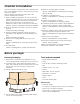
Parts included Location requirements Installation dimensions *URXQGHG 9 RXWOHW ORFDWHG LQVLGH WKH FDELQHW DERYH WKH RYHQ ULJKW VLGH VKRZQ DV H[DPSOH $ % & ' ) ( * PLQ ê PP You will find the installation hardware contained in packet with the unit.
Note: Take into account that the front and rear measurements of the appliance are not identical. Appliance dimensions Power Requirements The outlet must be properly grounded in accordance with all applicable codes. It can be installed anywhere inside the cabinet above the appliance, within reach of the power cord (approx. 24 in).
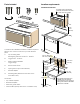
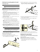
Install Appliance Removing the mounting plate No wall studs at corner holes Note: To avoid possible damage to the work surface or to the bottom of the appliance, cover the work surface. 1. Remove any remaining contents from the microwave oven cavity. 2. Remove the screws from the mounting plate. If wall stud is within 6¼" (159 mm) of the vertical centerline, only Room Venting (recirculation) or Roof Venting installations can be done.
Attaching the mounting plate to the wall Preparing rear wall 3. Attach toggle wings from the back of the mounting plate onto each bolt. Leave enough space for toggle wings to go through the wall and to open. CAUTION 9 Wear gloves to avoid cutting fingers on sharp edges. Note: Make sure the cabinet bottom is level. 1. Draw a vertical line on the wall at the center of the cabinet space. 2. Cabinet with front overhang: Draw a line on the back wall equal to the depth of the front overhang. 3.
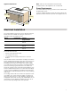
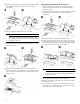
2. Carefully pull out the blower unit and rotate 90º so that fan blade openings are facing out the top of the microwave. Adapting microwave blower for wall venting 1. Remove and save the screws holding the blower motor and the blower plate. Lift up the blower plate and put it aside. 2. Carefully pull out the blower unit and rotate 90º so that fan blade openings are facing out the top of the microwave. 3. Place the blower unit back into the opening.
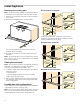
8. Attach the exhaust adapter to the rear of the oven by sliding it into the guides. Push in securely until it is in the lower locking tabs. Make sure the damper hinge swings freely. ▯ Use at least two people to install the microwave oven. Do not grip or use handle during the installation. When mounting the microwave oven, thread power cord through hole in bottom of top cabinet. Keep the cord tight and do not pinch it, especially when mounting flush to bottom of cabinet.
4. Insert the two remaining self-aligning screws through outer top cabinet holes. Turn two full turns on each screw. Hood exhaust When venting exhaust to the outside, hood exhaust ducts will be required. Read the following carefully. 5. Tighten center screw completely. 6. Tighten the outer two screws completely to the top of the microwave oven. Note: While tightening screws, hold the microwave oven in place against the wall and the top cabinet. 7.
Duct Pieces x Number used = 90° Elbow 10 ft (3 m) x = 45° Elbow 5 ft (1.5 m) x = 90° Elbow 25 ft (7.6 m) x = 45° Elbow 5 ft (1.5 m) x = Roof Cap 24 ft (7.3 m) x = x = Straight Duct 6" (152 mm Round or 3 1/4" x 10" 1 ft (0.3 m) (82 x 254 mm) Rectangular Equivalent Length Total Ductwork = * If a rectangular-to-round transition adapter is used, first make sure the damper hinge of the microwave swings freely.
Bosch® Support Before Calling Service Service See the Use and Care Manual for troubleshooting information. Refer to the “Statement of Limited Product Warranty” in the Use and Care Manual. To reach a service representative, see the contact information at the front of the manual or in the following section. Please be prepared with the information printed on your product data plate prior to calling. We realize that you have made a considerable investment in your kitchen.
Contenido nuIrsctoie de Definiciones de Seguridad ......................................... 15 INSTRUCCIONES DE SEGURIDAD IMPORTANTES .. 16 Seguridad con el manejo del electrodoméstico ......... 16 Códigos y normas de seguridad ................................... 16 Seguridad con la electricidad ......................................... 16 Seguridad con el microondas ........................................ 16 Seguridad relacionada con los equipos .......................
9 G E S E D INSTRUCCIONES DE SEGURIDAD IMPORTANTES LEA Y CONSERVE ESTAS INSTRUCCIONES INSTALADOR: DEJE ESTAS INSTRUCCIONES CON EL ELECTRODOMÉSTICO CUANDO HAYA FINALIZADO LA INSTALACIÓN. S E N O I C C U R T SA NE LI Y IMPORTANTE: CONSERVE ESTAS INSTRUCCIONES PARA USO DEL INSPECTOR DE ELECTRICIDAD LOCAL. ADVERTENCIA Si no sigue la información de este manual exactamente, se puede ocasionar un incendio o una descarga eléctrica que puede causar daños materiales o lesiones personales.
9 INSTRUCCIONES DE SEGURIDAD IMPORTANTES LEA Y CONSERVE ESTAS INSTRUCCIONES Antes de activar la alimentación eléctrica del microondas para realizar pruebas o inspecciones de servicio técnico en los compartimentos que generan microondas, verifique el magnetrón, la guía de onda luminosa o la línea de transmisión, y verifique que la alineación, la integridad y la conexión de la cavidad sean correctas.
Lista de verificación de instalación Use esta lista de verificación para verificar que haya completado cada paso del proceso de instalación. Esta lista puede ayudarlo a evitar errores comunes. Consulte las instrucciones detalladas para cada paso en las secciones que se encuentran a continuación de esta lista de verificación. 1. Antes de instalar el aparato, asegúrese de verificar que las medidas del gabinete sean correctas para su aparato y que estén presentes las conexiones eléctricas requeridas.
Herramientas y piezas necesarias ▯ ▯ ▯ ▯ ▯ ▯ ▯ ▯ ▯ ▯ ▯ Destornillador con cabeza Phillips Lápiz. Regla o cinta métrica, y borde recto. Taladro. Brocas: 3/16 pulg., 1/2 pulg., 5/8 pulg. Guantes. Sierra (de vaivén, de perforación o de punta). Buscapasadores o martillo. Gafas de seguridad. Nivel Cinta de tela y de enmascarar. Herramientas opcionales ▯ Escuadra de carpintero.
Medidas del aparato PLQ PP PD[ ʎ¼ʚ PP PLQ ê PP PLQ PP DEHUWXUD GHO JDELQHWH ë PP ê PP PLQ PP ʎ¼ʚ PP PLQ PP 3DUD REWHQHU UHQGLPLHQWR \ ILDELOLGDG ySWLPRV HO IDEULFDQWH UHFRPLHQGD GH D GH GLVWDQFLD D SHVDU GH OD GLVWDQFLD PtQLPD SHUPLWLGD VH REVHUYy ç¼ʚ PP Nota: Tome en cuenta que las mediciones delantera y trasera del aparato no son idénticos.
Montaje del electrodoméstico Retiro de la placa de fijación Nota: Para evitar posibles daños a la superficie de trabajo o a la parte inferior del aparato, cubra la superficie de trabajo. 1. Retire cualquier elemento que haya quedado en la cavidad del horno microondas. 2. Retire los tornillos de la placa de fijación. Posibles configuraciones de los pasadores de pared Estas representaciones muestran ejemplos de las configuraciones preferidas de instalación con la placa de fijación.
Pasadores de pared en ambos orificios de las esquinas 6. Únicamente para la instalación de ventilación de pared: Corte la sección sombreada “F” en la PLANTILLA DE LA PARED TRASERA utilizando una sierra de vaivén o de punta. 9 ATENCION Si el adaptador de escape está ubicado en el exterior, considere las medidas recomendadas; de lo contrario, el aire con grasa se descargará hacia la estructura del hogar. 7. Retire la PLANTILLA DE LA PARED TRASERA.
5. Ajuste con la mano los pernos para asegurarse de que las alas de anclaje de se hayan abierto contra el panel de yeso. 3. Vuelva a colocar la unidad del ventilador en la abertura. 9 ATENCION No tire del cableado de la unidad del ventilador ni lo estire. Asegúrese de que los cables no queden pinzados y de que estén asegurados en forma adecuada. 4. Vuelva a colocar la placa del ventilador y asegúrela con los tornillos que se retiraron en el paso 1. 6.
2. Retire la unidad del ventilador con cuidado y rótela 90º de modo que las aberturas de los álabes del ventilador miren hacia la parte superior del microondas. Preparación del gabinete 1. Retire la alimentación a la toma de corriente. 2. Retire todo el contenido del gabinete superior. 3. Pegue la PLANTILLA DEL GABINETE SUPERIOR con 3. Rote la unidad del ventilador 180º en el sentido contrario a las agujas del reloj. 4. Retire suavemente los cables de las ranuras.
▯ Contar con al menos dos personas para instalar el horno de microondas. No asir ni usar la empuñadura durante la instalación. 4. Insertar los dos tornillos autoalineables restantes en los agujeros exteriores del armario superior. Girar cada tornillo dos vueltas completas. Al montar el horno de microondas, pasar el cable de corriente a través del agujero en el fondo del armario superior. Mantener el cable tenso y no aprisionarlo, especialmente cuando se instale alineado con el fondo del armario.
El escape de la campana ha sido diseñado para acoplarse con un conducto rectangular estándar de 3¼ pulg. x 10 pulg. (82 x 254 mm). Si se requiere un conducto redondo, debe utilizarse un adaptador para la transición de rectangular a redonda. No utilice conductos que tengan un diámetro de menos de 6 pulg. (152 mm). Para el movimiento satisfactorio del aire, la longitud total del conducto rectangular de 3¼ pulg. x 10 pulg. (82 x 254 mm) o del conducto redondo de 6 pulg.
Piezas de conductos Tapa de techo x 24 pies (7.3 m) Conducto recto redondo de 6 pulg. (152 mm) o rectan1 pie (0.3 m) gular de 3 1/4 pulg. x 10 pulg. (82 x 254 mm) Cantidad utilizada x = x = Total de la red de conductos * Si se utiliza un adaptador de transición de rectangular a redonda, primero asegúrese de que la bisagra del regulador del microondas se mueva con libertad.
Soporte de Bosch® Antes de llamar al servicio Servicio técnico Para obtener información sobre resolución de problemas, consulte el Manual de uso y cuidado. Consulte la “Declaración de Garantía Limitada del Producto” en el Manual de uso y cuidado. Sabemos que usted ha realizado una inversión considerable en su cocina. Nos dedicamos a brindar asistencia a usted y a su aparato de manera que tenga muchos años de cocina creativa.
*9001152497* 9001152497 960301 1901 Main Street, Suite 600 • Irvine, CA 92614 • 800-944-2904 www.bosch-home.