26 en | Installation material and tools 5 DICENTIS Installation material and tools This section describes installation material such as cables, connectors and tools. Recommedations – Always use manufacturer specified installation products, materials and tools. – In general, use different cable ducts for the system network cables, audio cables and mains supply cables. – In public areas where people can touch or move above the connectors and cables, use metal protection covers. Warning! ! 5.
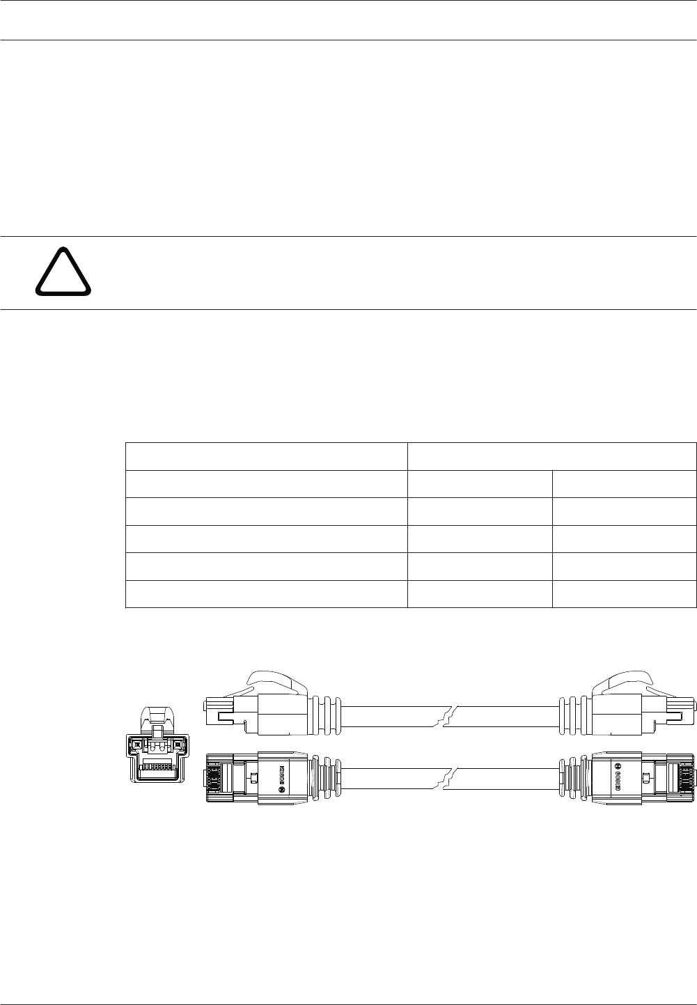
DICENTIS Installation material and tools | en 5.2 27 System Cable Connectors The connectors are used to make your own system network cables or to replace a connector. Two types of system cable connectors are available: DCNM-CBCON-I Installation Cable Connectors, page 28 and DCNM-CBCON-N Network Cable Connectors, page 28. Caution! ! Both connector types look similar but are different! So, only use the right type of connector with the right type of system cable.
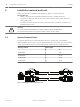
28 en | Installation material and tools 5.2.1 DICENTIS DCNM-CBCON-I Installation Cable Connectors The DICENTIS 50 Installation Cable Connectors DCNM‑CBCON‑I can only be used with the the DCNM-CB250 System Installation Cable, page 30 by using the DCNM-CBTK System Network Cable Toolkit, page 29. 5.2.
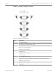
DICENTIS 5.3 Installation material and tools | en 29 DCNM-CBTK System Network Cable Toolkit The system network cable toolkit is used to connect the System Cable Connectors, page 27 to the DCNM-CB250 System Installation Cable, page 30 or System Network Cable, page 26. 1 2 Item Description 1 Power wiring tool. 2 Signal wiring tool. Table 5.2: Toolkit content Notice! Please consult the “custom length for system network cables” section on the DVD, which can be downloaded at: https://licensing.
30 en | Installation material and tools 5.4 DICENTIS DCNM-CB250 System Installation Cable The system installation cable, without connectors, is available in a length of 250 meters and is used for making your own system network cable. Refer also to the sections System Cable Connectors, page 27, DCNM-CBCON-I Installation Cable Connectors, page 28 and DCNM-CBTK System Network Cable Toolkit, page 29. Notice! The maximum system network cable length is: 100 m / 328,9 ft.
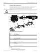
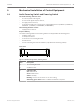
DICENTIS Mechanical installation of Central Equipment | en 6 Mechanical installation of Central Equipment 6.1 Audio Powering Switch and Powering Switch 31 The Audio Powering Switch is used: – to control system audio signals, – to route audio signals to/from devices, – to supply power to devices, – as an Ethernet switch to connect the PC and DICENTIS devices (DCNM-D / DCNM-DVT / DCNM-DSL / DCNM-DE / DCNM-MMD / DCNM-MMD2). The Powering Switch is used to: – supply power to devices.
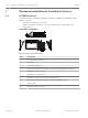
32 en | Mechanical installation of Central Equipment DICENTIS Rear view 1 2 3 4 5 6 7 8 10 12 11 13 15 14 17 16 9 19 18 20 Figure 6.2: Audio Powering Switch 9 10 12 13 14 15 17 16 18 19 20 Figure 6.3: Powering Switch Item Description 1, 5 XLR line outputs 1 and 2. 2, 6 RCA line outputs 1 and 2. 3, 7 XLR line inputs 1 and 2. 4, 8 RCA line inputs 1 and 2. 9 Mains inlet, mains switch and fuse holder. 10 Reset button. 11 Ground switch (grounded or floating).
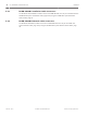
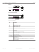
DICENTIS Mechanical installation of Central Equipment | en 33 How to install 1. Install the Audio Powering Switch or Powering Switch in a 19 inch device rack system or on a flat surface. Two 19 inch mounting brackets and four bottom feet are supplied with the Audio Powering Switch and Powering Switch. Refer to the following illustration. 2. Connect all required cabling. 3. Connect the mains supply. 2 1 3 Figure 6.
34 en | Mechanical installation of Contribution Devices DICENTIS 7 Mechanical installation of Contribution Devices 7.1 DICENTIS devices The DICENTIS devices (DCNM-D, DCNM-DVT, DCNM-DSL, DCNM-DE, DCNM-MMD, DCNMMMD2) are used to: – participate in a meeting or conference. – monitor and control a meeting or conference (chairperson use, depending on the configuration). DCNM-MMD / DCNM-MMD2 10 9 1 2 3 4 5 8 7 6 Figure 7.1: Front, top, rear and side views 2016.07 | V1.
Mechanical installation of Contribution Devices | en DICENTIS 35 DCNM-D / DCNM-DVT / DCNM-DSL / DCNM-DE Figure 7.2: Front, top, rear and side views Item Description 1 Two‑way loudspeaker. 2 Near Field Communication (NFC) reader. 3 Chairperson priority button, microphone mute button, or microphone request button for second participant. 4 Microphone request button. 5 Voting buttons. 6 Language selection buttons. 7 Language display. 8 4.3” capacitive touch screen. 9 3.
36 en | Mechanical installation of Contribution Devices DICENTIS Connecting DICENTIS devices The DICENTIS Conference System can be quickly and easily configured as a daisy‑chain configuration or as a star configuration: – Daisy‑chain configuration: Uses dedicated cabling, consisting of CAT‑5e cables including – Star configuration: Each DICENTIS device is connected with an individual standard two additional power conductors (see Typical system setup, page 8). CAT‑5e cable.
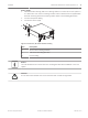
Mechanical installation of Contribution Devices | en DICENTIS 37 2 3 1 1 Figure 7.4: Bottom view DICENTIS devices (DCNM-D / DCNM-DVT / DCNM-DSL / DCNM-DE) Item Description 1 Screw insert for fixed installation. 2 2x RJ45 connection input/output for system power cable. 3 Cable guides. 4 USB connector, for future use (DCNM-MMD / DCNM-MMD2 only). See also – System Network Cable, page 26 – DCNM-CB250 System Installation Cable, page 30 Bosch Security Systems B.V.
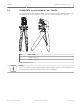
38 en | Mechanical installation of Contribution Devices 7.2 DICENTIS DICENTIS Microphones Both the DCNM‑HDMIC High Directive Microphone and DCNM-MICL/S Stem Microphone are typically used with the DICENTIS devices. 2 1 1 2 2 3 7 7 4 8 6 6 4 8 5 5 Figure 7.5: DCNM‑HDMIC and DCNM‑MICS / DCNM‑MICL front and bottom view 2016.07 | V1.4 | Number Description 1 LED indicator. 2 Microphone grill. 3 Adjustable stem (DCNM‑MICS / DCNM‑MICL). 4 Connection guidance. 5 Slider guidance.
Mechanical installation of Contribution Devices | en DICENTIS 39 How to connect or remove the microphone The microphone can be easily connected to the DICENTIS devices: 9 6 4 75 8 Figure 7.6: DCNM‑HDMIC or DCNM-MICS / DCNM-MICL connection To do so: 1. Gently guide the connection guidance (4) into the DICENTIS device microphone connector (9). 2. Gently push the connector plug (6) into the device microphone connector (9) until the connection lock (5) fits/click into place. 3.
40 en | Mechanical installation of Contribution Devices 7.3 DICENTIS DCNM-MMDSP Anti-reflection foil The DICENTIS anti‑reflection foil can be used to protect the tempered glass screen of a DICENTIS multimedia Device. Installation procedure 1. Use the included alcohol swab and the microfiber fabric to clean the device LCD screen before installation. 2. Peel the positioning adhesive release paper from the rear of anti‑reflection foil. 3.
DICENTIS 8 Installation Test | en 41 Installation Test An installation test is needed to prevent connection mismatches and find potential product defects at an early stage. Not to do so could result in a system malfunctioning. Each DICENTIS device has its own built‑in diagnostics, which can be used for faultfinding. The diagnostics starts as soon the DICENTIS device is powered on. The DICENTIS Conference System does not have to be configured with, and connected to, the system controller PC.
42 en | Installation Test DICENTIS – Downloading devices is not covered in this manual. Refer to the DICENTIS configuration manual on how to download the devices. Customer service If a fault cannot be resolved, please contact your supplier or system integrator, or go directly to your Bosch representative. 2016.07 | V1.4 | Hardware Installation Manual Bosch Security Systems B.V.
Bosch Security Systems B.V. Torenallee 49 5617 BA Eindhoven Netherlands www.boschsecurity.com © Bosch Security Systems B.V.