DICENTIS Conference System en Hardware Installation Manual
DICENTIS Table of Contents | en 3 Table of contents 1 Safety 4 2 About this manual 5 2.1 Intended audience 5 2.2 Alerts and notice signs 5 2.3 Copyright and disclaimer 5 2.4 Document history 6 3 System installation overview 7 3.1 Typical system setup 3.2 System extension 10 4 System installation design and planning 14 4.1 System capabilities 14 4.2 Hardware requirements 16 4.3 Power supply capacity calculation plan 17 4.3.
en | Safety 1 DICENTIS Safety Prior to installing or operating products, always read the Important Safety Instructions which are available as a separate multilingual document: Important Safety Instructions (Safety_ML). These instructions are supplied together with all equipment that can be connected to the mains supply. Safety precautions Some of the DICENTIS Conference System products are designed to be connected to the public mains network.
DICENTIS About this manual | en 5 About this manual 2 The purpose of this manual is to provide information required for installing the DICENTIS Conference System. This installation manual is available as a digital document in the Adobe portable document format (PDF). For more information, refer to the product related information on www.boschsecurity.com 2.1 Intended audience This hardware installation manual is intended for installers of a DICENTIS Conference System. 2.
en | About this manual 2.4 DICENTIS Document history Release date Documentation version Reason 2013.08 V1.0 1st edition. 2014.07 V1.1 2nd edition. New sections: 1 WEEE, 3.2 system ext, 5.2.1, 5.2.2. Sections updated: 2.4, 4.3.2, 5.2, 5.3, 5.4, 7.2 + DCNM‑MICx added. 2014.10 V1.2 3rd edition. Sections updated: 2.4, 3.2, 4.1 and 4.3.1. 2015.07 V1.3 4th edition. New section: 4.4, including sub-sections: 4.4.1, 4.4.2, and 4.4.3. Sections updated: 2.4, 3.1, 3.2, 4.1, 4.3, 4.3.1, 5.3, 5.4, 6.
DICENTIS 3 System installation overview | en 7 System installation overview It is advisable to participate in the DICENTIS Conference System training before you install, configure, prepare, and operate a DICENTIS Conference System. The DICENTIS Conference System is an IP based conference system which runs on an OMNEO compatible Ethernet network. It is used for distributing and processing audio, video and data signals.
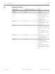
en | System installation overview 3.1 DICENTIS Typical system setup 1 2 9 5.1 8 7 8 8 8 4 8 6 6 8 6 3 6 6 5.2 5 Figure 3.1: Typical DICENTIS Conference System setup A typical DICENTIS Conference System consists of: 1. System server controller (PC): – 2. – 3. The heart of the system. It licenses functionality, configures and controls the system. Client PC: Can be used to: Manage meetings, prepare meetings and configure the system.
DICENTIS System installation overview | en 9 This system overview does not give information on redundant network options. For more information, refer to Redundancy options, page 21. Bosch Security Systems B.V. Hardware Installation Manual 2016.07 | V1.
en | System installation overview 3.2 DICENTIS System extension The DICENTIS Conference System is scalable from small to medium to large. This section describes what a small, medium and large system is and what the requirements are for these systems: A small DICENTIS Conference System (see Typical system setup, page 8) consists of: – up to 100 DICENTIS devices. – all DICENTIS devices in 1 subnet. – 1 DICENTIS Audio Powering Switch for the audio processing.
System installation overview | en DICENTIS 11 An ARNI (Audio Routed Network Interface) is used to increase the number of DICENTIS devices on a single subnet and to connect multiple DICENTIS system subnets. If more than one subnet is required, two types of an ARNI must be used. – OMN-ARNIS (ARNI‑S OMNEO interface): The ARNI‑S is required for increasing the system size above 100 DICENTIS devices. It supports up to 450 DICENTIS nodes in its subnet. It also acts as a DHCP server in its subnet.
en | System installation overview – DICENTIS This timer (or restriction) cannot be reached when there is no cable redundancy. This is because the power limitation will be reached before the max age restriction is reached. – 2016.07 | V1.4 | The timer can be reached when: – you use cable redundancy. – the system is incorrectly wired. Hardware Installation Manual Bosch Security Systems B.V.
DICENTIS System installation overview | en 13 Multi subnet DICENTIS Conference System The following figure illustrates a typical multi subnet DICENTIS Conference System with a total of 1200 DICENTIS devices. – The system is divided over four (4) subnets, where two (2) subnets having a maximum of 400 DICENTIS devices and an OMN-ARNIS are connected.
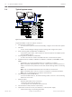
en | System installation design and planning 4 DICENTIS System installation design and planning Before you start to install system devices and connect system cabling, you should make a system design and planning: – – Familiarize yourself with the product and system capabilities. Make a cable (connection) plan: – Calculate the system network cable length. – Calculate the system power consumption. – Calculate the required power capacity of the system.
DICENTIS System installation design and planning | en 15 1 2 2 2 2 3 3 3 3 Figure 4.1: Example: Switch-levels Power supply capacity The total system network cable length and connected devices determine the required power supply capacity. The power within the DICENTIS Conference System is supplied by: – The Audio Powering Switch and the Powering Switch, or – Off‑the‑shelf PoE Ethernet switches.
en | System installation design and planning 4.2 DICENTIS Hardware requirements Switches The following minimal requirements apply to switches: – 1 Gbit or higher with hardware switching capabilities. – Quality of Service through differentiated services with 4 or more output queues and strict priority packet scheduling. – (Optional) IGMPv3 or IGMPv2 snooping. To optimize bandwidth usage, IGMP snooping can be used.
DICENTIS 4.3 System installation design and planning | en 17 Power supply capacity calculation plan How to start Notice! It is advisable to use the power calculation tool. The calculation tool is on the DVD supplied with the Audio Powering Switch and is also part of the DICENTIS software DCNM.iso file, which can be downloaded from the Bosch website at: https://licensing.boschsecurity.
en | System installation design and planning DICENTIS Ordering number Cable lengths m ft DCNM-CB02 2 6.56 DCNM-CB05 5 16.40 DCNM-CB10 10 32.81 DCNM-CB25 25 82.02 Table 4.2: Cable types and lengths Rear view 1 2 3 4 5 6 7 8 10 12 11 13 15 14 17 16 9 19 18 20 Figure 4.2: Audio Powering Switch 9 10 12 13 14 15 17 16 18 19 20 Figure 4.3: Powering Switch 2016.07 | V1.4 | Item Description 1, 5 XLR line outputs 1 and 2. 2, 6 RCA line outputs 1 and 2.
DICENTIS System installation design and planning | en Item Description 15, 17, 19 Socket 3, 4, 5 high power. 14, 16, 18, 20 Overload LED for sockets 2‑5: 19 Green: Power OK. Red: Overload. Remove cable and wait a few seconds for the system to reset the overload. Network and Power connector Max. power output (W) Max. devices Socket 1 (12) No power capacity --- Socket 2 (13) 15 1 Socket 3 (15) 144 40 Socket 4 (17) 144 40 Socket 5 (19) 144 40 Table 4.
en | System installation design and planning DICENTIS 2 1 Figure 4.4: Bottom view DICENTIS devices (DCNM-MMD / DCNM-MMD2) 1 2 Figure 4.5: Bottom view DICENTIS devices (DCNM-D / DCNM-DVT / DCNM-DSL / DCNM-DE) 2016.07 | V1.4 | Item Description 1 Network connector 2 Network/PoE connector Hardware Installation Manual Bosch Security Systems B.V.
DICENTIS 4.4 System installation design and planning | en 21 Redundancy options DICENTIS Conference Systems can be created with network redundancy. This ensures that the system will continue to work if: – a network cable is defective or accidentally disconnected. – one of the components fails.
en | System installation design and planning 4.4.1 DICENTIS Redundant cabling for DCNM‑APS/DCNM‑PS units This section describes how to create redundant cabling for DCNM-APS or DCNM-PS units. The maximum number of Ethernet devices in the loop (including the root switch) is 22. In a system with no Ethernet switch(es), the APS is the root switch.
DICENTIS 4.4.2 System installation design and planning | en 23 Redundant cabling for DCNM-APS2/DCNM-PS2 units This section describes how to create redundant cabling for DCNM-APS2 / DCNM-PS2 type units. The maximum number of Ethernet devices in the largest possible loop (including the root switch) is 22. In a system with no Ethernet switch(es), the APS is the root switch.
en | System installation design and planning DICENTIS Cabling possibilities (DCNM-APS2/DCNM- Limitations/requirements PS2) Create a redundant loop by connecting the The redundancy is for cable only. If the DICENTIS devices in a daisy chain DCNM-PS or DCNM-APS fails, all DICENTIS configuration from a high power socket on a devices connected to that unit will also fail. DCNM-PS2 / DCNM-APS2 to a high power socket on another DCNM-PS2.
DICENTIS 4.4.3 System installation design and planning | en 25 Redundant server PC System availability can be improved by connecting a redundant DICENTIS server PC and the associated components and cables to the DICENTIS Conference System. The maximum number of Ethernet devices in the largest possible loop (including the root switch) is 22.