
User's Manual


Engineered Solutions | ALLPLEX track Coordinator
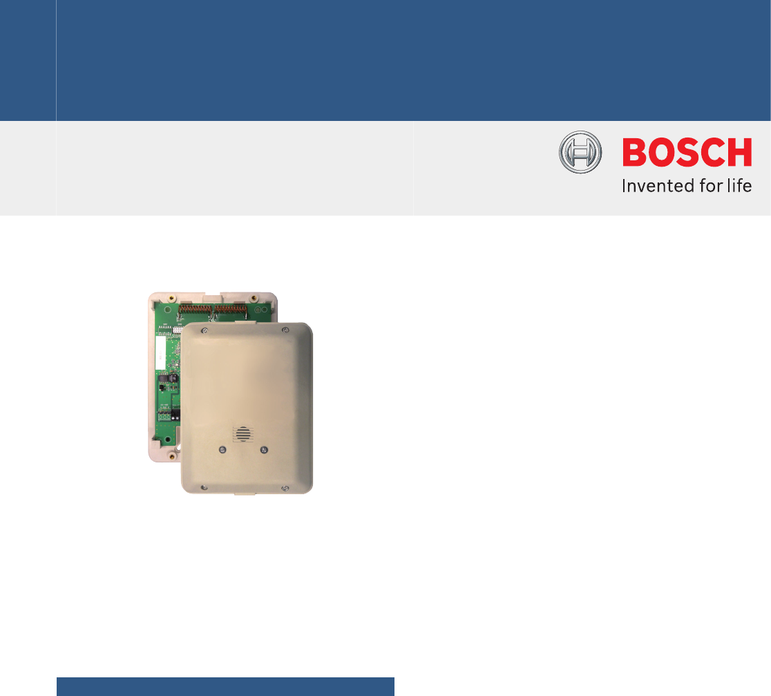
ALLPLEX track Coordinator
www.boschsecurity.com
u Device controller for up to 15 receivers
u Powered using Power over Ethernet (PoE)
u Wired TCP/IP to the host central console
u Wired (RS-485) or wireless communication to
receiver
u Selectable frequencies of 303.825 / 304 / 433.42
MHz
u Remote firmware upgradable via wired TCP/IP
u Built-in 2 inputs and 2 relay outputs
The ALLPLEX track coordinator is a device controller
for up to 15 ALLPLEX track receivers. Its primary
function is to monitor the receivers, and report
conditions and events to the central console over
wired Ethernet (TCP/IP). The coordinator can be
powered using Power over Ethernet (PoE).
Functions
Function during alarm
• When a receiver detects an alarm, it goes into an
Off‑Normal state. To quickly locate any devices which
might be in the Off‑Normal State, the coordinator
issues global commands that are interpreted
simultaneously by all of its devices approximately ten
times per second.
• The coordinator sends commands to specific devices
to determine the nature of the Off‑Normal condition.
During an alarm or test, the coordinator sends
commands to obtain the transmitter identification
number, transmitter battery condition, and received
signal strength.
• The alarm information is sent by the receiver to the
coordinator either by wired RS-485 or through
wireless radio frequency.
• The alarm information is then relayed by the
coordinator to the central console by wired Ethernet
(TCP/IP), where it graphically shows the identity and
location of the subscriber (user) sending the alarm.
Configuration
The coordinator identifies each receiver by its address.
The address is set during system installation using a
DIP switch on the receiver circuit board. Coordinators
communicate on the data bus with individual devices
by issuing commands, which contain the receiver’s
address.
Setup and testing
Upon setting up each coordinator and connected
devices, they can be tested remotely from the central
console. Also, each coordinator reports any problems,
such as low battery, immediately upon detecting them.
Alarm input and relay output control
The coordinator has two analog inputs and two relay
outputs. The analog inputs are monitored and support
4 state supervised modes. The coordinator can detect
short/open wiring conditions, and initiate an alarm if
the appropriate input devices are connected. Each
relay output provisions for normally open (NO),
normally closed (NC) and common (C) terminals.