
Installation Manual


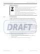
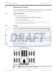
Table Of Contents

System Overview
The coordinator provides communication between the Central Console software and the many
receivers throughout the protected area. The receiver detects alarm signals from the
transmitter, and sends the signal to the coordinator either by wired RS-485 or through
wireless radio frequency. The coordinator forwards this information to the Central Console
software over wired Ethernet (TCP/IP), where the alarm will be processed accordingly. Each
coordinator (with its built-in receiver) also includes two analog inputs which support 4 state
supervised modes, and drivers for two relay outputs.
The receiver is designed to work with the Security Escort system throughout a protected area,
including building interiors. Each receiver contains a radio receiver to detect the transmissions
from transmitters, and a microcomputer to decode and interpret test and alarm messages.
Multiple receivers detect the same transmission and send the signal information to the
coordinator, so that the system can identify the transmitting information, including the device
and location. The receiver also monitors housing tampering and radio jamming, and reports
them to the coordinator.
Indoor coordinators/receivers are typically mounted on inside walls, and have one red and one
green LED. The green LED is used to indicate a successful test of a personal transmitter. The
red LED is illuminated during alarms. Each coordinator/receiver contains a piezo-electric
buzzer that can be activated if an alarm transmission is detected.
Outdoor coordinators/receivers are contained in small weatherproof boxes, typically mounted
on the sides of buildings and on light posts. Outdoor coordinators/receivers do not have the
visible red and green LED’s. For outdoors, the relay outputs can be connected to devices to be
used to acknowledge successful tests and alarms.
2
8 en | System Overview ALLPLEX track Coordinator & Receiver
2014.03 | V1.0.0 | F.01U.277.701 Installation Guide Robert Bosch (SEA) Pte Ltd