
Installation Manual
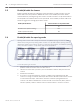


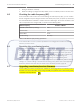


Table Of Contents

Troubleshooting the Device
This section offers troubleshooting guidance for situations when there are issues with the
coordinator/receiver. Upon powering up the device, there are visual indicators that provide
information about the current state or configuration of the devices. If these indicators behave
differently from what is expected, there could be issues that need to be addressed. The
following information can be helpful to determine potential issues.
Take note that the following LED indicators are only visible if the casing enclosure of the
device is temporarily removed:
– Power supply LED
– Tricolor LED
– Ethernet LED
– Power over Ethernet (PoE) LED (on the coordinator only)
Checking the power supply
When you power up the coordinator/receiver using the external DC input, the power supply
LED on the device will light up in orange. The LED will continue to illuminate as long as power
is supplied to the device. If the LED is not illuminated, there could be issues with the power
supply. Check that the operating input voltage is between the range specified (see Power
supply connector, page 16). If there is no power, check the cable or power supply to ensure
that it is not faulty. If there are no faults with the cable or power supply, check the
coordinator/receiver.
Checking Power over Ethernet (PoE)
Power over Ethernet (PoE) is only applicable for coordinators. Power for the coordinator can
be supplied via the Cat 5e cable using the PoE technology. When powered by the PoE, the PoE
LED will light up continuously in red color. If the LED is not illuminated, check that the Cat 5e
cable or the power sourcing equipment (for example, the network switch supplying the PoE)
is not faulty.
Checking Ethernet network issues
Ethernet network communication is only applicable for coordinators. The coordinator
communicates with the Central Console via Ethernet TCP/IP. If the coordinator uses an IP
address that is already in use by another device on the Ethernet network, an IP address
conflict occurs. This will render one or both the devices to be unable to connect to network
resources or perform other network operations.
If an IP address conflict is detected by the coordinator, the green and red LED will blink
continuously (500ms on, 500ms off). To rectify the issue, change the IP address of the
conflicting device using the Utility Tool of the Security Escort software, and blah blah blah (…
to be confirmed).
Checking the RS-485 communication
The coordinator and receivers communicate with each other via RS-485 by default. The
tricolor LED on the device will blink in pink light every 3 seconds as long as RS-485
communication is available. If the RS-485 communication is broken, the coordinator and
receivers will switch to radio frequency (RF) as the communication channel. As a result, the
behavior and color of the tricolor LED will no longer be the same (blink in pink light every 3
seconds). To troubleshoot RS-485 communication, check that the following is working:
1. RS-485 is enabled on the host system configuration.
6
6.1
6.2
6.3
6.4
26 en | Troubleshooting the Device ALLPLEX track Coordinator & Receiver
2014.03 | V1.0.0 | F.01U.277.701 Installation Guide Robert Bosch (SEA) Pte Ltd