
Installation Manual
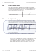


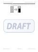


Table Of Contents

2. Activate the transmit mode on the receiver. Set switch number 2 on dip switch SW3 to
the ON position. Power the receiver from a 12 VDC source. The receiver will start
transmitting messages to the coordinator continuously. This communication is indicated
by the blinking LED.
3. If the receiver is within the range, the LED will continue to blink. Move the receiver away
from the coordinator until the green LED stops blinking. This indicates that the receiver is
now beyond the maximum range. Move back to the last location where the coordinator is
able to receive the transmission from the receiver. This location marks the maximum
spacing between the coordinator and the receiver. The distance between the coordinator
and the receiver should not exceed 25 m (80 ft.) indoors and 90 m (300 ft.) outdoors.
Figure 5.3: Coordinator and Receiver Spacing
1
LED of the coordinator stops blinking
when the receiver is moved past this
point
3 Receiver at maximum range
2 Coordinator 4 Receiver beyond maximum range
Setting the jumpers for RS-485 communication loop
For RS-485 communication, it is necessary to include the end of line jumper settings on the
last receiver to have a stable communication channel. Set the jumper for the coordinator and
the last receiver as of below:
1. For the coordinator, locate the jumper block J5 and set the jumper over the jumper pins 1
and 2 (default setting on coordinators).
5.8
24 en | Setting the Switches and Jumpers ALLPLEX track Coordinator & Receiver
2014.03 | V1.0.0 | F.01U.277.701 Installation Guide Robert Bosch (SEA) Pte Ltd