
Installation Manual


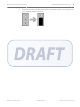


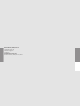
Table Of Contents

Figure 5.2: Receiver Spacing
1
Receiver 1 stops sounding the test
beeps when receiver 2 is moved past
this point
3 Receiver 2 at maximum range
2 Receiver 1 4 Receiver 2 beyond maximum range
Enable/disable the transmit mode
Transmit mode can be used to verify the maximum acceptable spacing of receivers from the
coordinator using the radio frequency communication. When the transmit mode is enabled on
the receiver, it will communicate with the coordinator continuously. Enable or disable the
transmit mode by setting switch number 2 on dip switch SW3. Transmit mode is disabled by
default, where switch number 2 is set to the OFF position. To enable the transmit mode, set
switch number 2 on dip switch SW3 to the ON position.
Enable/disable Transmit Mode Switch Number on Dip Switch SW3
2
Disable Transmit Mode (default setting) OFF
Enable Transmit Mode ON
Table 5.8: Enable or disable the transmit mode on dip switch SW3
The following is applicable when using the radio frequency as the communication channel.
Transmit Mode is enabled with switch number 2 of dip switch 3 on the AT receiver (see the
ALLPLEX track Coordinator & Receiver Installation Guide). Only transmissions with an adequate
receive margin will light up the green LEDs. This indicates the maximum acceptable spacing of
the AT receiver.
To test the spacing of the receivers:
1. Activate the spacing mode on the coordinator (see Enable/disable the spacing mode, page
22). Set switch number 1 on dip switch SW3 to the ON position.
5.7
ALLPLEX track Coordinator & Receiver Setting the Switches and Jumpers | en 23
Robert Bosch (SEA) Pte Ltd Installation Guide 2014.03 | V1.0.0 | F.01U.277.701