
Installation Manual
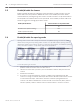


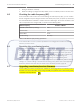


Table Of Contents

Enable/disable the buzzer
Enable or disable the buzzer by setting the buzzer dip switch. Set switch number 6 on dip
switch SW2 to the OFF position to disable the buzzer. Once disabled, the buzzer will be
muted at all times, including during alarm events. Set switch number 6 on dip switch SW2 to
the ON position to enable the buzzer to be operational. Once enabled, the buzzer will sound
whenever triggered accordingly by the alarm events.
Enable/disable Buzzer Switch Number on Dip Switch SW2
6
Disable Buzzer (default setting) OFF
Enable Operational Buzzer ON
Table 5.6: Enable or disable the buzzer on dip switch SW2
Enable/disable the spacing mode
Spacing mode can be used to verify the maximum acceptable spacing of receivers. Enable or
disable the spacing mode by setting switch number 1 on dip switch SW3. Spacing mode is
disabled by default, where switch number 1 is set to the OFF position. To enable the spacing
mode, set switch number 1 on dip switch SW3 to the ON position.
Enable/disable Spacing Mode Switch Number on Dip Switch SW3
1
Disable Spacing Mode (default setting) OFF
Enable Spacing Mode ON
Table 5.7: Enable or disable the spacing mode on dip switch SW3
To test the spacing of receivers:
1. Mount the first receiver (receiver 1). Set switch number 1 on dip switch SW3 to the ON
position. Power the receiver from a 12 VDC source.
2. Take the second receiver (receiver 2) and a transmitter a distance away from the first
receiver.
3. Activate the transmitter.
4. If receiver 1 sounds the test beep, receiver 2 is within range. Repeat this test until
receiver 1 no longer sounds the test beeps. Move back to the last location where receiver
1 received the test beeps. This location marks the maximum spacing between the
receivers. The distance between the receivers should not exceed 25 m (80 ft.) indoors
and 90 m (300 ft.) outdoors. Mount receiver 2 at this location or closer to receiver 1.
5.5
5.6
22 en | Setting the Switches and Jumpers ALLPLEX track Coordinator & Receiver
2014.03 | V1.0.0 | F.01U.277.701 Installation Guide Robert Bosch (SEA) Pte Ltd