
Installation Manual
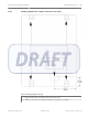

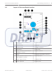
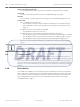
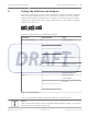
Table Of Contents

Notice!
It is recommended to power off the coordinator/receiver before you change the dip switch
settings. Upon completing the changes, power up the devices. The new settings will only take
into effect once the coordinator/receiver completed a power reset cycle.
Setting the loop address
Use the address dip switch to configure the RS-485 loop address of the receiver. Each
coordinator/receiver on a loop must have its own unique address. Only addresses 0 through
15 are valid.
The coordinator always uses address 0. You do not need to set the address for the
coordinator. Therefore, the dip switch SW1 used for setting addresses is not available on the
coordinator. The receivers use addresses 1 to 15. Set the address using dip switch SW1.
Configure the four switches from the left, 1, 2, 3 and 4 as the address of the device.
Address Switch Number on Dip Switch SW1
1 2 3 4
0
(used for
coordinator only)
OFF OFF OFF OFF
1
(default setting
for receiver)
ON OFF OFF OFF
2 OFF ON OFF OFF
3 ON ON OFF OFF
.
.
.
.
.
.
.
.
.
.
.
.
.
.
.
15 ON ON ON ON
Table 5.2: Address settings on dip switch SW1
Setting the radio frequency (RF)
Use the radio frequency (RF) switches on dip switch SW2 to configure the RF of the device.
Set the two switches from the left, 1 and 2 according to the following table.
Radio Frequency Switch Number on Dip Switch SW2
1 2
304 MHz (default setting) OFF OFF
303.825 MHz OFF ON
5.1
5.2
20 en | Setting the Switches and Jumpers ALLPLEX track Coordinator & Receiver
2014.03 | V1.0.0 | F.01U.277.701 Installation Guide Robert Bosch (SEA) Pte Ltd