
Installation Manual

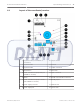
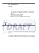
Table Of Contents

Setting the Switches and Jumpers
There are three dip switches on the receiver, namely SW1 on the left, SW2 in the middle and
SW3 on the right. Dip switch SW1 is not mounted on the coordinator. Therefore, only dip
switches SW2 and SW3 are available on the coordinator. Use the dip switches to configure
settings like the address of the device and the radio frequency, or the operation settings like
usage of soft or hard reset.
Figure 5.1: Dip switches
The usage of the dip switches are explained as of below:
Dip Switch
Switch Number Usage
SW1 (receiver only) 1 Address of Device
2
3
4
5 Not Used
6
SW2 1 Frequency Selection
2
3 Hard/Soft Reset Mode
4 Baud Rate
5
6 Disable/Enable Buzzer
SW3 1 Spacing Selection
2 Transmit Mode
3 Not Used
4
5
6
Table 5.1: Usage of dip switches
Usage of the dip switches will be explained in detail in the respective sections.
Notice!
Take note that switch number 5 and 6 on dip switch SW1 and switch number 3, 4, 5 and 6 on
dip switch SW3 are currently not being used.
5
ALLPLEX track Coordinator & Receiver Setting the Switches and Jumpers | en 19
Robert Bosch (SEA) Pte Ltd Installation Guide 2014.03 | V1.0.0 | F.01U.277.701