
Installation Manual
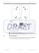
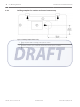
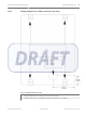

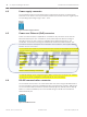
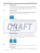
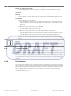
Table Of Contents

Power over Ethernet (PoE) LED
– The LED will light up in red as long as the coordinator is powered by the PoE input.
Green LED
– For every successful transmitter test, the LED will briefly light up in green.
Red LED
– For every alarm or specific system test in progress, the LED will briefly light up in red.
Tricolor LED
– Upon coordinator/receiver start up
– the LED blinks a number of times in white to indicate the current radio frequency
(RF) configuration as set by the dip switch (see Checking the radio frequency (RF),
page 27)
– Coordinator/receiver communicating via RS-485
– the LED blinks in pink every 3 seconds
– Coordinator/receiver communicating via RF when RS-485 is not working
– the LED blinks in green for any transmission events if the signal strength is excellent
– the LED blinks in blue for any transmission events if the signal strength is average
– the LED blinks in red for any transmission events if the signal strength is poor
– If there is no communication between the coordinator and receiver, the LED does not
light up.
Notice!
The power supply, PoE and tricolor LEDs are only visible if you remove the casing enclosure.
Tamper switch
To protect the coordinator/receiver against unauthorized access, an additional interface to
detect tamper contact is used. The tamper switch is triggered when the coordinator/receiver
is not covered in the casing enclosure. This event is monitored and reported to the Central
Console Software where any subsequent actions are determined by the configured software
settings. It is recommended that the coordinator/receiver should be covered in the casing at
all times.
Reset button
A reset button is available on the coordinator/receiver. This button can be used to perform a
hard or soft factory reset based on the associated dip switch setting (see Selecting the hard/
soft reset mode, page 21). Depending on the hard or soft reset, pressing it will clear specific
sets of configuration for the device. For more information, please refer to Resetting the
coordinator/receiver, page 27.
4.9
4.10
18 en | Layout and Wiring of the Device ALLPLEX track Coordinator & Receiver
2014.03 | V1.0.0 | F.01U.277.701 Installation Guide Robert Bosch (SEA) Pte Ltd