
Installation Manual
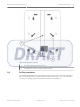
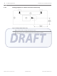
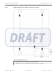

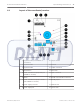
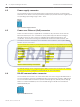
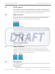
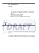
Table Of Contents

RS-485 jumpers
The coordinator and receivers use RS-485 multi-drop communication channels between the
device boards. It is necessary to include end-of-line jumper settings on the last receiver to
have a stable communication channel (see Setting the jumpers for RS-485 communication loop,
page 24). The jumper blocks are identified as J5 on the coordinator/receiver.
Input connectors
Two 2-pin connectors on the left side of the coordinator/receiver provide terminal points for
wiring from input devices. The terminal strips are identified as Input1 and Input2 on the
coordinator/receiver. There are two terminals for each input point.
Figure 4.4: Input Connectors
Each input point supports four-state supervised mode. To detect the four states, there are
special values allowed for potential drop depending on the resistors used. The coordinator/
receiver can also detect short and open wiring conditions and initiate an alarm if the
appropriate devices are connected.
Figure 4.5: Circuit Diagram for Resistors
R
S
= R
P
= 2.2 kΩ ¼W
Output connectors
Two 3-pin connectors provide terminal points for connection of external devices. The
connectors are identified as OUT 1 and OUT 2 on the coordinator/receiver. The output
terminals are Form-C type relay dry contacts. For each relay, Normally Closed (NC), Normally
Open (NO) and Common (C) terminals are provided.
Figure 4.6: Output Connectors
LED indicators
The following section describes the behaviors of the various LEDs upon device start up and
during system operation.
Power supply LED
– The LED will light up in orange as long as the coordinator/receiver is powered by the DC
input.
4.5
4.6
4.7
4.8
ALLPLEX track Coordinator & Receiver Layout and Wiring of the Device | en 17
Robert Bosch (SEA) Pte Ltd Installation Guide 2014.03 | V1.0.0 | F.01U.277.701