
Installation Manual
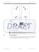
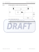

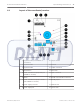
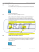
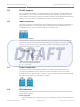
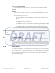
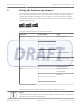
Table Of Contents

Power supply connector
The coordinator/receivers can be powered by an external 12V DC input. It consists of two
terminals: one of which is used to provide the positive input, and the other the negative input.
The operating input voltage range is 10.8 – 13.2V.
Figure 4.2: Power Supply Connector
Power over Ethernet (PoE) connector
Power over Ethernet (PoE) is applicable to coordinators only. Receivers do not have the
Ethernet interface ports. The coordinators can be powered by PoE without needing an
external DC input. The PoE connector is identified by the label PoE Ethernet on the
coordinator. Connect the PoE using the standard Cat 5e Ethernet cable and above. PoE
provides the maximum total power of 12.95 Watt to the coordinator, and complies with the
IEEE802.3af class 0 standard.
The coordinator also sends any received data from the receivers or transmitters to the Central
Console Software via the Ethernet cable. The coordinator is pre-configured with the following
default IP settings:
IP Settings
Value
IP Address 192.168.1.100
Subnet Mask 255.255.255.0
Gateway 192.168.1.1
Port 20000
Table 4.1: Default IP Settings of Coordinator
The default settings can be changed using the Utility Tool from the Security Escort software.
See the Security Escort Installation and Setup Manual for more information.
RS-485 communication connector
The coordinator and receivers can communicate with each other using the RS-485 interface.
The communication connector is identified by their 3 terminal points, namely A, GND and B.
The recommended data transmission speed is 19200 bps @ 1km (default) and 115 kbps @
500m. For outdoor installations, the recommended wiring for RS-485 communication is
shielded twisted-pair.
Figure 4.3: RS-485 Connector
4.2
4.3
4.4
16 en | Layout and Wiring of the Device ALLPLEX track Coordinator & Receiver
2014.03 | V1.0.0 | F.01U.277.701 Installation Guide Robert Bosch (SEA) Pte Ltd