
Installation Manual

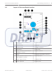
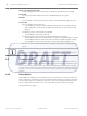
Table Of Contents

Layout of the coordinator/receiver
Figure 4.1: Layout of coordinator/receiver
1
Dip switch SW1 (not available on
coordinator)
10 Tamper switch
2 Dip switch SW2 11 Red LED
3 Dip switch SW3 12 Output connectors
4 Reset button 13 Green LED
5 Power over Ethernet (PoE) LED (not
available on receiver)
14 Input connectors
6 Buzzer 15 RS-485 communication connector
7 Power over Ethernet (PoE) connector
(not available on receiver)
16 RS-485 jumpers
8 Power supply connector 17 Ethernet LED
9 Power supply LED 18 Tricolor LED
4.1
ALLPLEX track Coordinator & Receiver Layout and Wiring of the Device | en 15
Robert Bosch (SEA) Pte Ltd Installation Guide 2014.03 | V1.0.0 | F.01U.277.701