ALLPLEX track Coordinator & Receiver ATX-COR-MT01 & ATX-RCV-MT01 en Installation Guide
ALLPLEX track Coordinator & Receiver Table of Contents | en 3 Table of contents 1 Copyright, Safety and Warranty 5 1.1 Copyright information 5 1.2 Important safety notes 6 1.3 Safety precautions 7 1.4 FCC information 7 2 System Overview 8 3 Mounting the Device 9 3.1 Indoor installation 9 3.1.1 Spacing 9 3.1.2 Mounting height 9 3.1.3 Multi-floor installations 3.2 Outdoor installation 10 3.2.1 Spacing 10 3.2.2 Mounting height 10 3.2.3 Overhangs/eaves 10 3.
en | Table of Contents ALLPLEX track Coordinator & Receiver 7 Appendices 28 7.1 Differences between hard and soft reset mode on the coordinator/receiver 28 2014.03 | V1.0.0 | F.01U.277.
ALLPLEX track Coordinator & Receiver Copyright, Safety and Warranty | en 1 Copyright, Safety and Warranty 1.1 Copyright information 5 All rights reserved. No part of this manual may be reproduced, stored in a retrieval system, or transmitted in any form or by any means, electronic, mechanical, photocopying, recording, or otherwise, without the prior written permission of BOSCH SECURITY SYSTEMS. This manual is provided pursuant to a license agreement containing restrictions on their use.
1.2 en | Copyright, Safety and Warranty ALLPLEX track Coordinator & Receiver Important safety notes 1. Read, Follow, and Retain Instructions – All safety and operating instructions must be read and followed properly before putting the unit into operation. Retain instructions for future reference. 2. Consider all Warnings – Adhere to all warnings on the unit and in the operating instructions. 3. Accessories – Use only accessories recommended by the manufacturer or those sold with the product.
ALLPLEX track Coordinator & Receiver 1.3 Copyright, Safety and Warranty | en 7 Safety precautions Disposal Your Bosch product has been developed and manufactured using highquality materials and components that can be reused. This symbol means that electronic and electrical devices that have reached the end of their working life must be disposed of separately from household waste. In the EU, separate collecting systems are already in place for used electrical and electronic products.
2 en | System Overview ALLPLEX track Coordinator & Receiver System Overview The coordinator provides communication between the Central Console software and the many receivers throughout the protected area. The receiver detects alarm signals from the transmitter, and sends the signal to the coordinator either by wired RS-485 or through wireless radio frequency.
ALLPLEX track Coordinator & Receiver 3 Mounting the Device | en 9 Mounting the Device Choose a mounting location based on the previous site survey. Mount the coordinator/receiver as close as possible to the location found with the test coordinator/receiver. Use the following sections as a guideline for coordinator/receiver mounting and spacing. 3.1 Indoor installation Select a mounting location that: 3.1.1 – provides a clear line-of-sight of the protected area, if possible.
en | Mounting the Device 3.2 ALLPLEX track Coordinator & Receiver Outdoor installation Select a mounting location that: – – provides a clear line-of-sight of the protected area. is away from metallic objects such as chain-link fences and electrical transformers. If coverage is required near such items, perform testing near them to determine the potential need for additional receivers. 3.2.1 – is 3 m (10 ft.) above grade.
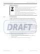
ALLPLEX track Coordinator & Receiver Mounting the Device | en 11 Figure 3.2: Back of indoor enclosure 3.4 1 Use with single-gang electrical boxes 2 Use with 8.9 cm (3½ in.) square electrical boxes Drilling templates Use the following templates for mounting the outdoor enclosure. For enclosure with bottom entry, see Drilling template for outdoor enclosure bottom entry, page 12. For enclosure with rear entry, see Drilling template for outdoor enclosure rear entry, page 13.
en | Mounting the Device 3.4.1 ALLPLEX track Coordinator & Receiver Drilling template for outdoor enclosure bottom entry Figure 3.3: Drilling template bottom entry 1 Align template with mounting hole squares on box 2 Drill here, 25 mm (1 in.) diameter maximum; 19 mm (¾ in.) conduit. 3 Bottom entry 2014.03 | V1.0.0 | F.01U.277.
ALLPLEX track Coordinator & Receiver 3.4.2 Mounting the Device | en 13 Drilling template for outdoor enclosure rear entry Figure 3.4: Drilling template rear entry Robert Bosch (SEA) Pte Ltd 1 Align template with mounting holes on backside of box. 2 Drill here, 25 mm (1 in.) diameter maximum; 19 mm (¾ in.) conduit. Installation Guide 2014.03 | V1.0.0 | F.01U.277.
4 en | Layout and Wiring of the Device ALLPLEX track Coordinator & Receiver Layout and Wiring of the Device Danger! Apply the electrical power only after all connections are completed and inspected. This section identifies and locates the key components on the coordinator/receiver. 2014.03 | V1.0.0 | F.01U.277.
ALLPLEX track Coordinator & Receiver 4.1 Layout and Wiring of the Device | en 15 Layout of the coordinator/receiver Figure 4.
4.2 en | Layout and Wiring of the Device ALLPLEX track Coordinator & Receiver Power supply connector The coordinator/receivers can be powered by an external 12V DC input. It consists of two terminals: one of which is used to provide the positive input, and the other the negative input. The operating input voltage range is 10.8 – 13.2V. Figure 4.2: Power Supply Connector 4.3 Power over Ethernet (PoE) connector Power over Ethernet (PoE) is applicable to coordinators only.
ALLPLEX track Coordinator & Receiver 4.5 Layout and Wiring of the Device | en 17 RS-485 jumpers The coordinator and receivers use RS-485 multi-drop communication channels between the device boards. It is necessary to include end-of-line jumper settings on the last receiver to have a stable communication channel (see Setting the jumpers for RS-485 communication loop, page 24). The jumper blocks are identified as J5 on the coordinator/receiver. 4.
en | Layout and Wiring of the Device ALLPLEX track Coordinator & Receiver Power over Ethernet (PoE) LED – The LED will light up in red as long as the coordinator is powered by the PoE input. Green LED – For every successful transmitter test, the LED will briefly light up in green. Red LED – For every alarm or specific system test in progress, the LED will briefly light up in red.
ALLPLEX track Coordinator & Receiver 5 Setting the Switches and Jumpers | en 19 Setting the Switches and Jumpers There are three dip switches on the receiver, namely SW1 on the left, SW2 in the middle and SW3 on the right. Dip switch SW1 is not mounted on the coordinator. Therefore, only dip switches SW2 and SW3 are available on the coordinator. Use the dip switches to configure settings like the address of the device and the radio frequency, or the operation settings like usage of soft or hard reset.
en | Setting the Switches and Jumpers ALLPLEX track Coordinator & Receiver Notice! It is recommended to power off the coordinator/receiver before you change the dip switch settings. Upon completing the changes, power up the devices. The new settings will only take into effect once the coordinator/receiver completed a power reset cycle. 5.1 Setting the loop address Use the address dip switch to configure the RS-485 loop address of the receiver.
ALLPLEX track Coordinator & Receiver Setting the Switches and Jumpers | en Radio Frequency 21 Switch Number on Dip Switch SW2 1 2 433.42 MHz ON OFF Invalid setting ON ON Table 5.3: Radio frequency (RF) settings on dip switch SW2 Once configured, you can confirm the RF settings every time you power up the coordinator/ receiver by observing the tricolor LED. For more information, refer to Checking the radio frequency (RF), page 27. 5.
5.5 en | Setting the Switches and Jumpers ALLPLEX track Coordinator & Receiver Enable/disable the buzzer Enable or disable the buzzer by setting the buzzer dip switch. Set switch number 6 on dip switch SW2 to the OFF position to disable the buzzer. Once disabled, the buzzer will be muted at all times, including during alarm events. Set switch number 6 on dip switch SW2 to the ON position to enable the buzzer to be operational.
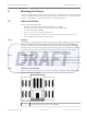
ALLPLEX track Coordinator & Receiver Setting the Switches and Jumpers | en 23 Figure 5.2: Receiver Spacing 1 Receiver 1 stops sounding the test 3 Receiver 2 at maximum range beeps when receiver 2 is moved past this point 2 Receiver 1 5.7 4 Receiver 2 beyond maximum range Enable/disable the transmit mode Transmit mode can be used to verify the maximum acceptable spacing of receivers from the coordinator using the radio frequency communication.
en | Setting the Switches and Jumpers 2. ALLPLEX track Coordinator & Receiver Activate the transmit mode on the receiver. Set switch number 2 on dip switch SW3 to the ON position. Power the receiver from a 12 VDC source. The receiver will start transmitting messages to the coordinator continuously. This communication is indicated by the blinking LED. 3. If the receiver is within the range, the LED will continue to blink.
ALLPLEX track Coordinator & Receiver 2. Setting the Switches and Jumpers | en 25 For the last receiver, locate the jumper block J5 and set the jumper over the jumper pins 2 and 3 (default setting on receivers). Robert Bosch (SEA) Pte Ltd Installation Guide 2014.03 | V1.0.0 | F.01U.277.
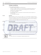
6 en | Troubleshooting the Device ALLPLEX track Coordinator & Receiver Troubleshooting the Device This section offers troubleshooting guidance for situations when there are issues with the coordinator/receiver. Upon powering up the device, there are visual indicators that provide information about the current state or configuration of the devices. If these indicators behave differently from what is expected, there could be issues that need to be addressed.
ALLPLEX track Coordinator & Receiver 6.5 Troubleshooting the Device | en 27 2. Wiring of RS-485 is not faulty. 3. Baud rate settings (configured via dip switch) on the coordinator/receivers are the same. Checking the radio frequency (RF) If the coordinator and receivers are communicating via radio frequency (RF), you can confirm the RF configuration by checking the tricolor LED visually. Every time you power up the device, the LED will illuminate and blink a number of times in white light.
en | Appendices ALLPLEX track Coordinator & Receiver 7 Appendices 7.1 Differences between hard and soft reset mode on the coordinator/receiver The table below lists the different configurations that were cleared when performing the hard or soft resets.
Robert Bosch (SEA) Pte Ltd 11 Bishan Street 21 573943 Singapore Singapore www.boschsecurity.