
User Manual
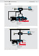


Table Of Contents

6/12 Bosch Rexroth AG
LLC Load Limiting Control
RE 95310/01.09
Variant LLCA
Figure 4: Inputs and outputs on the controller (variant LLCA, configuration without CAN-bus interface)
LLCA connection diagram (without CAN bus)
10 A
30
+12 V/+24 V
+
-
31
3 A
3)
1 A
2 )
2 )
2 )
2 )
C
D
B
E
A
H
1 )
8
20
9
21
13
41
42
27
1
2
28
32
33
43
44
17
7
18
22
46
47
38
35
36
34
45
52
24
50
51
29
3
15
31
30
RS-232
RxD
TxD
37
48
10
11
30 15
6)
49
Ignition lock
7)
Voltage supply for
the electronics
Power supply for the
power outputs
Speed sensor
(optional)
LS pressure
(optional)
1)
Short, low-resistance connection from a case screw to the device ground or vehicle ground
2)
Separate ground connection from solenoid return line to battery (chassis possible)
3)
Separate fuses recommended for switches, sensors and electronics
5)
Sensor supply voltage for potentiometers and active sensors
6)
Observe maximum current consumption where proportional solenoids and switched outputs are controlled simultaneously
7)
Can be used as switch inputs if connected externally to GND
Sensor supply
5)
2 x 5 V/30 mA
Frequency inputs
Proportional outputs
Main pump 1
Main pump 2,
valve control for
limp home mode
or valve control for
precision mode
(optional)
Error
lamp
Signal lamp for
automatic speed
reduction
Switched outputs
Low-side
measurement
input
Voltage
inputs
Current
inputs
5 V
constant voltage
Temperature inputs
Switch inputs
Ground
connection,
case
Diagnostics
connector
for BODAS service
External specification
of power reduction or
specification for
precision mode
(optional)
Angle position
sensor on
accelerator pedal
or injection linkage
(optional)
Teaching set speeds (optional)
Power sharing mode (optional)
Power mode 2 (optional)
Power mode 2 (optional)
Reserved