
User Manual
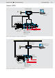


Table Of Contents

Bosch Rexroth AG
RE 95310/01.09
LLC Load Limiting Control
5/12
Important features
• The ratio in which the power reduction is distributed be-
tween pump 1 and pump 2 in the event of a limit load can be
set as a parameter. Depending on the parameter setting, the
power reduction may be distributed evenly between the two
pumps, or the division may be asymmetrical.
A second distribution value of the power reduction can be
set as an optional additional parameter. An external switch
can then be used to switch between the two methods
(power sharing mode switch).
• The total maximum permitted pump power can be reduced
using an external potentiometer.
• An additional temperature mode is possible if a diesel engine
with a CAN-bus interface is used. If the temperature passes
above or below the limits set as parameters, power is re-
duced to a user-definable level.
• Power modes: Switches between three different permissible
hydraulic powers. These arise from the permissible speed
drops that are specified differently for each power mode.
• Precision mode: A valve is controlled depending on the posi-
tion of a dial potentiometer. The drop in LS pressure caused
by the valve can be used to slow operating functions, e. g. for
precision work.
• Automatic speed reduction: If no operating function is
requested for a longer period of time, the diesel engine
switches to idle mode to reduce fuel consumption. For this
purpose, a pressure switch (normally closed contact) must
be installed in an appropriate location. At low LS pressure,
the pressure switch closes, signaling to the controller that
automatic speed reduction is requested.
• If a diesel engine with a CAN-bus interface is used, the pres-
ent output currents from pump 1 and pump 2 are sent via the
CAN bus every 100 ms. This includes the power sharing set
externally with a potentiometer and, if relevant, error mes-
sages.
• The second proportional solenoid output can be used for
limp home mode or for controlling a valve for the fine mode
(parameterizable). Under normal circumstances this output
produces a constant 100 %; this value falls to 0 % in the
event of an error. Thus, the pumps can be switched by an
external valve to an operating mode that enables the device
to be run with no electronics.
• The inputs and outputs of the controller are monitored (for
cable break, short-circuit). In the event of an error or if the
safety switch is actuated, the drive is stopped immediately.
All of the above errors as well as errors in the CAN commu-
nication with the diesel engine and excessively high or low
engine temperature can be indicated by a flashing code on a
connected error lamp.
• All errors that occur are stored in the controller and can also
be read later in plain text form using BODAS service.
Important parameters
For a diesel engine with a CAN-bus interface:
• Diesel engine data (specified speed and actual speed via
CAN bus, specified torque and actual torque via CAN bus,
dynamic behavior, permissible speed drop)
• CAN bus (baud rate, controller addresses, signal priorities)
• Configuration (number of pumps and limp home mode,
power sharing, hydraulic concept, specified-speed source)
• Minimum and maximum magnetic current for pumps 1 and 2
• Load limiting control (dynamic controller data)
• Function (minimum/maximum temperatures, power reduc-
tion)
For a diesel engine without a CAN-bus interface:
• Diesel engine data (actual speed from sensor, number of
teeth on flywheel, dynamic behavior, permissible speed drop)
• Potentiometer for specified speed and power sharing
• Configuration (number of pumps and limp home mode,
power sharing, hydraulic concept, specified speed source)
• Minimum and maximum magnetic current for pumps 1 and 2
• Load limiting control (dynamic controller data)
Variant LLCA