
User Manual
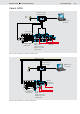


Table Of Contents

4/12 Bosch Rexroth AG
LLC Load Limiting Control
RE 95310/01.09
Functional description
Figure 3 illustrates how the load limiting control works:
• The load limiting control calculates the current speed drop
of the diesel engine from the speed setting and the diesel
characteristic depending on the set power mode.
The power modes are used to switch between three different
permissible hydraulic powers. The switch is performed using
switches which are connected to the controller.
In the case of diesel engines with a CAN interface, torque
can alternatively be used for control purposes.
• The load limiting control compares the current speed drop
with the parameterizable limit values. Different limit values
can be parameterized for different specified speeds.
In case of diesel engines with a CAN interface, the
temperature of the diesel engine can also be taken into
account in this evaluation. As soon as the temperature value
passes out of a parameterizable range, the limit value for the
drop in engine speed is further reduced.
By externally specifying the reduction in power, the maximum
power can be further limited. This is specified by means of a
limit potentiometer connected to the controller.
• As long as the total of the hydraulic powers does not exceed
the installed diesel power, the speed drop will not exceed
the parameterized limit values. The load limiting control will
not intervene.
• If, however, the diesel engine speed drop exceeds the limit
value, the load limiting control will intervene and reduce the
pump power.
The controller will calculate the available pump power as a
control value.
• The pump power distributor shares the pump power deter-
mined by the controller among the connected pumps.
The percentages used for sharing the available power
between the connected pumps can be parameterized.
A switch on the controller also allows the operator to switch
between two different distribution patterns.
Instead of pump 2, a valve can also be connected and
parameterized for limp home mode or for precision mode.
Figure 3: How the LLCA load limiting control works
Safety switch
Specified
speed
Actual speed
Temperature
Ext. power
limiting
Power
sharing 1
Power
sharing 2
Limp home mode
activated
Calculation
Speed drop
Pump
power
sharing
Load limiting
controller
Evaluation
Speed drop
Pump 1
Pump 2
Power
mode 2/3
Variant LLCA