
User Manual
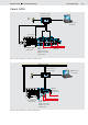


Table Of Contents

2/12 Bosch Rexroth AG
LLC Load Limiting Control
RE 95310/01.09
Variant LLCA
With the LLCA electronic load limiting control, it is possible to
design the size of the diesel engine in the hydraulic system for
the average power requirement and to reduce the power input
of the individual consumers (pumps) in the event of an over-
load. Thus, the load limiting control ensures optimum use of
power from the diesel engine with varying loads.
The electronic load limiting control supports different hydraulic
concepts and different diesel engine configurations. These
concepts can be used in any combination.
The electronic load limiting control is designed for controlling
variable displacement pumps in an open hydraulic circuit.
A distinction is made between the following hydraulic concepts
for the purpose of control:
• With negative ID, the hydraulic system includes one or two
A11VO variable displacement pumps or variable double
pumps A8VO or A20VO, each with hydraulic power and load
limiting controllers (LG1, LE, LA1).
Each pump is set to 100 % of the available diesel power.
The controller controls the pump controller (LE) and/or the
pressure reduction valves (DRE) directly; the latter turn
down the setting on the pump power controller (LG1, LA1)
by means of an increased pilot pressure.
• With positive ID, the hydraulic system includes one or two
A10VO variable displacement pumps with an FHD pump
controller.
The total installed pump powers exceeds the diesel engine
power.
The controller controls the pressure reduction valves (DRE)
which in turn override the pilot pressures of the pumps,
thereby reducing the flow rate.
A third, uncontrolled pump can be used with both hydraulic
concepts. This pump has priority in the system. As a result, it
receives the power it requires with no reduction. Whatever pow-
er remains available is then divided between pumps 1 and 2.
Two different diesel engine configurations can be used:
• In the case of diesel engines without a CAN-bus inter-
face, the controller receives the diesel engine's specified
speed from an angle sensor (accelerator pedal position as
specified speed) or from a fixed speed value set in the con-
troller. The actual speed is measured using a speed sensor
on the starter gear rim.
• In the case of diesel engines with a CAN-bus interface,
the controller receives the necessary data for the load limit-
ing control (specified and actual speed and/or torque and
engine temperature) directly via the CAN bus.
It is also possible to use a combination of analog sensors
and CAN-bus data.
Type code
AS/ LLC 10
01 02 03 04
Type
01
Application software
AS/
Software
02
Load Limiting Control
LLC
Variante A
03
Load limiting control for two pumps
Option: CAN bus, Option: Constant speed control
A
Variante B
03
Load limiting control for one pump, Option: Slew drive
Option: Power mode (switchable diesel power and speed drop)
B
Version
04
LLCB
10
LLCA
30
Ordering information
The AS/LLC application software must only be used with the RC2-2/20 controller (variant B) or RC2-2/21 controller (variant A)
and other add-on components (see page 11). When placing an order, the hardware and software type codes should be linked with
a "+".
Example: RC2-2/21+AS/LLCA30