
User Manual
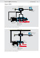


Table Of Contents

10/12 Bosch Rexroth AG
LLC Load Limiting Control
RE 95310/01.09
Figure 8: Inputs and outputs on the controller (variant LLCB)
LLCB connection diagram
2
)
2
)
41
1
42
2
33
32
37
48
28
A
B
31
30
29
1
)
51
50
17
52
TxD
RS232 RxD
+L
C
D
B
E
A
G
F
H
+5 V / 15 mA
47
46
49
2
)
1 A
3
)
12V/
24 V
0 V
8 A
27
10
11
Ignition lock
with starter
non-repeat
unit
Speed sensor
Angle position
sensor on
accelerator pedal or
injection linkage
Teach
Maximum power
Working pump
Control block -
slew drive shaft
Error lamp
Diagnostics
connector
for BODAS serivce
1
)
Short, low-resistance connection from the plug connector and one housing screw to the device ground
2
) Separate ground connection from the solenoid return line to the battery (chassis also possible)
3
) Separate fuses for switches and sensors
Power supply
Supply of the power
outputs
Error detection for
potentiometers 1K-5K
Power mode 2
Power mode 3
Variant LLCB