
User Manual
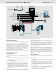
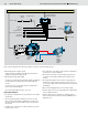

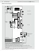
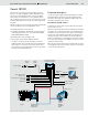
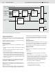
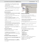
Table Of Contents

Bosch Rexroth AG
Open and Closed Loop Speed Control SPC RE 95300/12.07
9/16
To acknowledge errors, the drive potentiometer must be
moved to the neutral position and the direction switches
must be turned off.
• Monitoring the inputs and outputs
The lines for setpoint inputs and outputs and the proportional
solenoid outputs are monitored for wire breaks and short
circuits.
In case of an error or if the safety switch is actuated, the
drive is turned off immediately.
Important features
• The acceleration and deceleration times can be set separate-
ly for both directions of drive rotation. They can be switched
on and off with a switch in the vehicle.
• A switch in the vehicle can be used to switch the closed
loop speed control on or off.
• A sensor in the hydraulic motor (integrated or external)
measures the actual speed of the drive.
• Accurate closed loop speed control is possible even at low
speeds.
• Safety functions such as the start enable monitor the operat-
ing behavior of the drive.
• The inputs and outputs of the controller (e.g. drive potenti-
ometer) are monitored (for cable breakage and short circuit).
In case of an error or if the safety switch is actuated, the
drive is turned off immediately.
• All errors that occur are stored in the controller and can
also be read out later in plain text using the BODAS service
diagnostic tools.
Important parameters
• Hydraulic motor data (actual speed, sensor HDD2)
• Drive potentiometer for set speed
• Confi guration (acceleration and deceleration times, dead
band, speed regulator, special function)
• Minimum and maximum solenoid current for pump forwards
and backwards
Parameter Settings and Diagnostics
The parameters to be set for commissioning the SPCC closed
loop speed control are easy to adjust with the BODAS service
PC software.
For diagnostics and troubleshooting, you can use BODAS
service to display the most important process variables and
error messages.
Required Components
The following electronic components are required:
• RC2-2/20 controller with mating connector (RE 95200)
• Software: AS/SPCC, Version 10
• Drive lever HG104GF/11 (RE 95041)
• HDD2 speed sensor with mating connectors (RE 95135),
preferably integrated in the hydraulic motor
• Safety switch (emergency stop)
The following additional electronic components can be used:
• Potentiometer for setpoint specifi cation (alternative to the
drive lever)
• Switch for turning the time ramps on and off
• Switch for turning the closed loop speed control on and off
• Direction switches
The following hydraulic components are required:
• Variable pump with corresponding control device
A4VG…EP (RE 92003) or
A10VG…EP (RE 92750)
• Fixed motors
A2FM (RE 91001) or
A2FE (RE 91008) or
A4FM (RE 91120) or
A10FM (RE 91172) or
MCR (RE 15205 … 15209)
The following are required for commissioning and service:
• BODAS service PC software (RE 95086)
• BODAS service connection cable
• Diagnostics socket