
User Manual
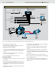

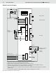
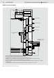
Table Of Contents

8/16 Bosch Rexroth AG
Open and Closed Loop Speed Control SPC RE 95300/12.07
Setpoint specification
The drive potentiometer sets the output speed. This can be a
potentiometer on the drive lever or an external potentiometer.
Two direction switches in the vehicle set the direction of drive
rotation (forwards or backwards).
Working behavior
The working behavior of the drive is controlled by three para-
meters:
• The drive potentiometer supplies the setpoint for the output
speed.
• The direction switch determines the direction of rotation
(forwards or backwards).
• The acceleration behavior selected by the time ramp set-
tings determines how fast the control changes at the PWM
output. The time ramps can be adjusted separately for ac-
celeration and deceleration and for forwards and backwards
rotation. The time ramps can be switched on and off using a
switch in the vehicle.
The drive potentiometer is in the neutral position if it is posi-
tioned within an adjustable range around the zero position.
This range is called the dead band.
When the drive potentiometer is in the neutral position, the
PWM outputs for controlling the proportional solenoids of the
pump are switched off.
When it is moved to a position outside of the dead band, the
current at the respective PWM output (for forwards or back-
wards rotation) increases depending on the position of the
potentiometer, the direction switch and the set time ramp.
The corresponding proportional solenoids of the pump are
activated.
Special function
Closed loop speed control enables the control of a special
function. This can be any other function, for example another
drive. When the speed of the hydraulic motor exceeds a
selected switching level, the special function switches on.
Safety functions
Various options are available for monitoring the working
behavior:
• Start enable
Start enable is used to prevent the drive from starting
unintentionally.
After switching on the controller (ignition on), the starting
condition must be satisfied in order for the switching signal
for start enable to activate. Only then can the drive be
started. This means that the start enable signal must be
incorporated in the start control of the diesel engine.
The starting condition is satisfied when
– the drive potentiometer is in the neutral position,
– the direction switches are off and
– the hydraulic motor is at a downtime.
Closed loop speed control on/off
Drive potentiometer
Forwards direction
of rotation
Pump
Switch
output
Start
enable
Time ramps
Safety switch (also switches off RC)
Actual speed of hydraulic
motor
Backwards direction
of rotation
Ramp active
Preparation of
setpoint
Preparation of
actual value
Closed loop
speed
controller
Special
function
E
M
E
R
G
E
N
C
Y
S
T
O
P
Switch
output
Figure 6: How the SPCC closed loop speed control works