
User Manual
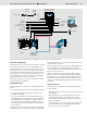
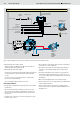

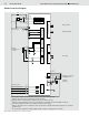
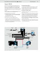
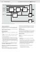
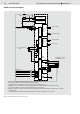
Table Of Contents

Bosch Rexroth AG
Open and Closed Loop Speed Control SPC RE 95300/12.07
7/16
Variant SPCC
The electronic closed loop speed control (Speed Control,
SPCC) is an easily configurable software application for the
closed loop control of hydraulic drives. Here, the hydraulic
drive consists of a pump and one or more hydraulic motors.
The closed loop speed control serves to keep the drive speed
constant, independent of the speeds of the diesel engine and
the pump.
The SPCC electronic closed loop speed control is designed to
control a variable pump in a closed hydraulic circuit.
The following hydraulic concept is used:
• A variable pump A4VG or A10VG with electroproportional
control EP together with one or more fixed motors A2FM,
A2FE, A4FM, A10FM or MCR
The following diesel engine design is used:
• Diesel engine with or without CAN bus interface
The SPCC closed loop speed control does not use the
CAN bus. Neither the set speed nor the actual speed of the
diesel engine is necessary for closed loop speed control.
The closed loop control is dependent on the set speed and
actual speed of the hydraulic motor.
Functional Description
In order to keep the output speed of hydraulic drives constant
and independent of the diesel engine speed and the pump
speed, the swivel angle of the hydraulic variable pump is ad-
justed by electroproportional control.
Closed loop speed control
A switch in the vehicle can be used to switch the closed loop
speed control on or off.
When the closed loop speed control is switched on, the follow-
ing applies: The set speed of the drive is specified by the drive
potentiometer. The actual speed of the drive is measured by a
speed sensor in the hydraulic motor. When the actual speed
changes, the pump control and, thus, the swivel angle of the
pump are regulated in such a way that the flow stays constant.
As a result, the output speed of a hydraulic motor connected to
the pump is held constant.
When the closed loop speed control is switched off, the pump
control adjusts itself in a linear fashion using the set time ramps
to reach the desired setpoint.
Figure 5: Typical configuration for the SPCC closed loop speed control
Power supply
Ignition
switch
Controller RC2-2/20
with SPCC software
BODAS service
PC software
Diagnostics
socket
CAN bus
interface
Safety
switch
Speed sensor
Engine Variable pump
A4VG...EP or
A10VG...EP
RS232
Fixed motor
A2FM or
A2FE or
A4FM or
A10FM or
MCR
Ramp active
Closed loop speed control on/off
Forwards
Backwards
Drive potentiometer
Start enable
Special function