
User Manual
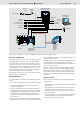
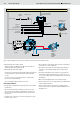

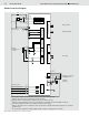
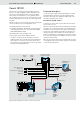
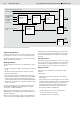
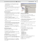
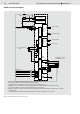
Table Of Contents

Bosch Rexroth AG
Open and Closed Loop Speed Control SPC RE 95300/12.07
3/16
Figure 1: Typical configuration for the SPCA, closed hydraulic circuit, diesel engine without CAN bus interface
Setpoint specification
The output speed or the volume flow is specified by a joystick.
The joystick can be a drive lever or a simple potentiometer.
It is also possible to use two joysticks in the vehicle. The sec-
ond joystick can also be a lever or a simple potentiometer. A
switch can then be used to switch between the two joysticks,
for example if there is one potentiometer in the driver‘s com-
partment and another at the rear of the vehicle. Switching is
only possible when the drive is at a downtime.
Two direction switches in the vehicle set the direction of drive
rotation (forwards or backwards).
Working behavior
The working behavior of the drive is controlled by three para-
meters:
• The output speed setpoint value is specified by the joystick.
• The direction switch determines whether the drive runs
forwards or backwards.
• The acceleration behavior selected using the time ramp
settings determines how quickly the control is changed at
the PWM output to the pump. The time ramps can be set
separately for the joystick deflection (without open loop
speed control intervention) and with open loop speed con-
trol intervention.
The joystick is in the neutral position if it is positioned within
a range about the zero position. This range is called the dead
band. A fixed value has been set for the dead band in the soft-
ware and cannot be altered.
When the joystick is in the neutral position, the PWM outputs
for controlling the proportional solenoids of the pump are
switched off (there are two PWM outputs in the closed circuit
and one in the open circuit).
When the joystick is moved to a position outside the dead
band, the current at the respective PWM output (forwards or
backwards direction of rotation) increases depending on the
position of the joystick, the direction switch and the set time
ramp. The corresponding proportional solenoid of the pump is
controlled.
Safety functions
Various options are available for monitoring working behavior:
• Start condition
The start condition is used to prevent the drive from starting
unintentionally.
After switching on the controller (ignition on), the joystick
that has been switched to active must be in the neutral
position and the direction switches must be off so that the
drive can be started.
To acknowledge errors, the joystick that has been switched
to active must be moved to the neutral position and the
direction switches must be turned off.
Power supply
Ignition
switch
Controller RC2-2/21
with SPCA software
BODAS service
PC software
Diagnostics
socket
CAN bus
interface
Error lamp
Safety
switch
Speed sensor
Engine
Variable pump
A4VG...EP or
A10VG...EP
RS232
Fixed motor
A2FM or
A2FE or
A4FM or
A10FM or
MCR
Joystick 1
Joystick 2 active
Speed control on/off
Forwards
Backwards
Joystick 2