
User Manual
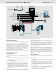
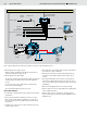

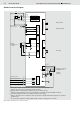
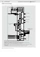
Table Of Contents

10/16 Bosch Rexroth AG
Open and Closed Loop Speed Control SPC RE 95300/12.07
Figure 7: Inputs and outputs on the controller for SPCC
SPCC Connection Diagram
2
)
41
1
42
2
33
32
37
48
28
30
1
)
51
50
17
40
52
39
TxD
RS232 RxD
CAN H
CAN L
C
D
B
E
A
G
F
H
+5V
10
11
34
47
46
49
36
35
38
5)
+5V
5)
2
)
31
2
)
29
2
)
15
4
)
27
10 A
0 V
30
+12 V/+24 V
+
−
31
3 A
3 )
6 )
1 A
30 15
Voltage supply
electronics
Supply for
power outputs
Speed sensor
(hydraulic motor)
Drive potentiometer,
1 - 5 kW
Ramp active
Closed loop speed control on/off
Forwards
Backwards
Frequency inputs
Sensor supply
Voltage inputs
Current inputs
Switch inputs
Inter-
face 1
Reserved
Inter-
face 2
Pump forwards
Pump backwards
Special function
Diagnostics connector
for BODAS service
Start enable
Proportional
outputs
Switched
outputs
1)
Short, low-resistance connection from a case screw to the vehicle ground
2)
Separate ground connection to battery (chassis possible)
3)
Separate fuses recommended for switches and sensors and electronics
4)
CAN bus: 120 W termination resistor recommended (see installation instructions RDE 90 300-01)
5)
5V / ground outputs may also be used alternatively as sensor supply
6)
Observe maximum current consumption where proportional solenoids and switched outputs are controlled
simultaneously
7)
The terminals are labeled according to DIN 72 552. This does not apply for the controller.
Safety switch
Ignition switch
7)