
User Manual
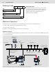
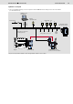
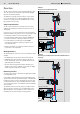
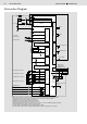

Table Of Contents

8/8 Bosch Rexroth AG
AFC Fan Control
RE 95360/06.08
© This document, as well as the data, specifi cations and other information set
forth in it, are the exclusive property of Bosch Rexroth AG. It may not be repro-
duced or given to third parties without its consent.
The data specifi ed above only serve to describe the product. No statements
concerning a certain condition or suitability for a certain application can be de-
rived from our information. The information given does not release the user from
the obligation of own judgment and verifi cation. It must be remembered that our
products are subject to a natural process of wear and aging.
Subject to change.
Bosch Rexroth AG
Hydraulics
Mobile Electronics Product Unit
Elchingen plant
Glockeraustraße 2
89275 Elchingen, Germany
Tel.: +49-7308-82-0
Fax: +49-7308-72-74
info.brm-ak@boschrexroth.de
www.boschrexroth.com/brm
Safety Instructions
• The suggested circuits do not imply any technical liability
for the system on the part of Rexroth.
• The lines used for speed sensors are to be shielded. The
shield must be connected to the electronics on one side
or to the machine or vehicle ground via a low-resistance
connection.
• Cables to the electronics must not be routed close to other
power-conducting lines in the machine or vehicle.
• All connectors must be unplugged from the electronics
during electrical welding operations.
• The electronics may only be tested with the proportional
solenoids connected.
• The proportional solenoids must not be wired with
spark-suppression diodes.
• Switching solenoids at the outputs of the controller RC do
not need to be connected to spark-suppression diodes.
• Other inductive loads that are in the system but not con-
nected to the controller RC must be connected to spark-
suppression diodes.
• In order to preserve the warranty, any installation or replace-
ment of the RC software (fl ash EPROM) must be performed
by Rexroth personnel.
• Please observe the operating instructions contained in
RE 95360-01-B.