
User Manual
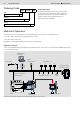
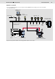
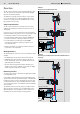
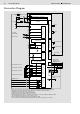

Table Of Contents

6/8 Bosch Rexroth AG
Fan Control AFC
RE 95360/06.08
CAN H
CAN L
8)
8)
8)
8)
8)
8)
10 A
30
+12 V/+24 V
+
-
31
3 A
3)
1 A
6)
6)
7 )
7 )
7 )
7 )
2 )
2 )
2 )
2 )
C
D
B
E
A
H
F
G
1 )
4 )
8
20
9
21
13
41
42
27
1
2
28
32
33
43
44
17
7
18
22
46
47
38
35
36
34
45
40
39
25
26
52
24
50
51
29
3
15
31
30
7)
RS-232
RxD
TxD
120 Ohm
37
49
48
10
11
30 15
Connection Diagram
Ground
1)
Short, low-resistance connection from a case screw to the device ground or vehicle ground
2)
Separate ground connection from solenoid return line to battery (chassis possible)
3)
Separate fuses needed for switches and sensors
4)
CAN bus: termination resistor 120Ω recommended
5)
Sensor supply for potentiometer and active sensors
6)
Separate ground connection for current source to battery, control unit GND (pin 38/49) possible.
7)
If ≥ 5V is applied to the input, all power outputs are off.
8)
Can be used as switch inputs if connected externally to GND.
9)
The terminals are labeled according to DIN 72 552. This does not apply for the controller.
Ignition lock
10)
Voltage supply for electronics
Supply for power
outputs
Proportional outputs
Frequency inputs
Voltage inputs
Temperature sensor 1
Fan 1
Error lamp
Digital input 1
Diagnostics
connector for
BODAS-service
Ground connection
for case
5V
constant voltage
reserved
Temperature sensor 2
Temperature sensor 3
Temperature sensor 4
Digital input 2
Reversing valve
Fan 2
Speed, fan 1
Speed, fan 2
Current inputs
Digital input 3
Digital input 4
Switch inputs
Temperature inputs
Low-side
measurement
input
Switched outputs
Standstill valve
Sensor supply
5)
2 x 5V/30 mA