
User Manual
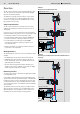
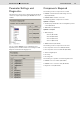

Table Of Contents

Bosch Rexroth AG
RE 95360/06.08
Fan Control AFC
5/8
Digital Output
In addition to controlling the pumps, the fan control can also
be used to control a digital output. This is done by comparing
the temperature values measured with the sensors with the set
switching thresholds and the calculating the switching signal.
• If the measured value falls below the lower temperature
threshold, the digital output is set to 0.
• If the measured value exceeds the upper temperature
threshold, the digital output is set to 1.
• The range between the two thresholds is used as the
hysteresis.
Safety Functions
The lines for the temperature inputs and proportional solenoid
outputs are monitored for wire breaks and short circuits.
In the event of an error, the maximum setpoint is set and,
thus, the fan fully controlled.
In the event of overheating, an error lamp is set and an
overheating warning is given.
Important Features
• Up to four temperature sensors
There are default caracteristic curves for Bosch temperature
sensors. A user-specifi c characteristic curve can be defi ned
by parameter settings.
• CAN bus communication
• Up to four digital outputs to infl uence the setpoints via
functions defi ned by parameter settings.
• Speed measurement via digital inputs
• Up to two independent fan drives
• Variable response via time ramps.
• Digital output can be actuated via temperature thresholds
• Reversing function
• Safety function
• Diagnostics function
Any faults that occur are logged in the control unit and
can be read later on using
PC software BODAS-service
in plain text.
Main Parameters
• Sensor curves
• Time ramps for temperature inputs
• Temperature thresholds for setpoints
• Digital input function module
• Switching threshold for digital output
• Output time ramps for fans
• Minimum and maximum solenoid current for pumps
• Change or direction
• CAN bus communication