
User Manual
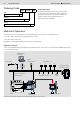
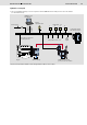
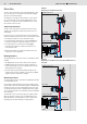
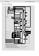

Table Of Contents

4/8 Bosch Rexroth AG
Fan Control AFC
RE 95360/06.08
Function
The fan control controls up to two fans independently of each
other. For each fan, four temperature inputs and four digital
inputs are monitored separately.
The illustrations on pages 2 and 3 show the control system
for one fan with four sensors and four digital inputs. The in-
structions for a single fan are described below. The second
fan operates in the same way.
Setpoint Specifi cation
The fan control calculates the setpoint power of the fan by
reading in the temperature and the fan speed via sensor or
CAN signals.
For the sensors, you can set parameters for the temperatures
at which the different fan power levels are required. This results
in a setpoint specifi cation for each temperature input:
• If a measured value falls below the associated lower tem-
perature threshold, the setpoint specifi cation is set to 0.
• If a measured value exceeds the associated upper
temperature threshold, the setpoint specifi cation is set
to its maximum value.
• Between thresholds, the setpoint specifi cation increases
in proportion to the temperature.
Working Behavior
The working behavior of the fan control is controlled by various
variables:
• The digital inputs can be used to infl uence this setpoint.
• A digital input used to activate the change in direction of
the fan. Alternatively, this can be activated
after an interval
defi ned by parameter settings
.
• The time ramps at all inputs and outputs determine how
quickly the fan control is modifi ed or how quickly the digital
output responds to temperature changes.
Reversing Function
The "Reversing" function is activated via a digital input (switch)
or an adjustable interval.
It is possible for both fi xed pump systems and variable pump
systems. When used, the fan is fi rst brought to a standstill. The
fl ow direction of the oil is then changed by the fan motor. This
is realized either with the aid of a 4/3-directional valve (variant
1) or a 4/2-directional valve in combination with a fan standstill
valve (variant 2).
The minimum control current may change to a different value
when the direction of rotation is reversed depending on the
different dynamics of the fan blades in order to prevent over-
speeding of the fan motor during reversing operation.
Variant 1:
Reversing via 4/3-directional valve
ba
Pump control ED
DSM speed sensor
Reversing Standstill
Variant 2:
Reversing via 4/2-directional valve and standstill valve on
the pump
a
Pump control ED
DSM speed sensor
Reversing
Standstill