
User Manual

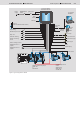
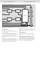
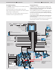

Table Of Contents

16/16 Bosch Rexroth AG Mobile Hydraulics
Dual Path Control DPC
RE 95 325/03.04
© All rights reserved by Bosch Rexroth AG,
also for the event of registration of industrial property rights. All rights of use,
including copyright and right of distribution, reserved.
The information contained herein is intended to serve purely as a product
description. The information we have provided cannot be used as evidence of a
particular aspect or of suitability for a particular purpose. This information does
not release the user from his responsibility to perform his own assessments and
tests. Please note that our products are subject to the natural processes of aging
and wear.
We reserve the right to make changes.
Bosch Rexroth AG
Mobile Hydraulics
Product Unit Mobile Electronics
Elchingen Plant
Glockeraustrasse 2
89275 Elchingen, Germany
Phone +49 (0) 73 08 82-0
Facsimile +49 (0) 73 08 72 74
info.brm-me@boschrexroth.de
www.boschrexroth.com/brm
Components Required
The following electronic components are required:
• RC6-9/20 control unit with mating connector (RE 95200)
• AS/DPCB software, Version 10 or
AS/DPCC software, Version 10
• HG104 joystick (RE 95041) with direction switches
• GP200 steering potentiometer
• HDD speed sensors (RE 95135) with mating connectors
• WS1 angle sensor (RE 95140) with mating connector
• Switch for slip steering
• Switch for selecting travel behavior modes
• Emergency stop switch
The following electronic components can be used:
• Potentiometer (1-5 kOhm) for limiting the maximum travel
speed
• Speed sensor IDR (RE 95130) with mating connector for
displaying two external speeds (
variant B) or speeds of the
additional functions (variant C)
• Stop/Go switch
• Variant B only: Angle sensor WS1 (RE 95140) with mating
connector as steering sensor
• Variant B only: Switch for automatic steering
• Variant B only: Switch for mounting position of steering sen-
sor
• Variant C only: Potentiometer (1-5 kOhm) for assignment
setpoint for additional functions
• Variant C only: Switch for additional functions
• Variant C only: Display DI2/11 (RE 95089) for defining
parameters and diagnosis
The following hydraulic components are required:
• Variable displacement pump with suitable control device
A4VG…EP (RE 92003) or
A10VG…EP (RE 92750)
• Variable displacement motor with suitable control device
A6VM…EZ (RE 91604) or
A6VE…EZ (RE 91606) or
A10VM…EZ (RE 91703)
• Variant C only (additional functions):
Variable displacement pump with suitable control device
A4VG…EP (RE 92003) or
A10VG…EP (RE 92750)
The following items are required for commissioning and
service:
• Diagnostics socket (RE 95085)
• BODEM PC software with BODEM connecting cable
(RE 95085)
• BB-3 control panel with BB-3 connecting cable (RE 29798
and RE 95080)
Safety Instructions
• The suggested circuits do not imply any technical liability of
Rexroth for the system.
• The safety instructions in RE 90301-01-B must be observed.
• Leads for speed sensors must be shielded. The shield must
be connected to the electronics on one side or to the ma-
chine or vehicle ground via a low-resistance connection.
• Cables to the electronics must not be routed close to other
power-conducting cables in the machine or vehicle.
• Sufficient distance from radio systems must be maintained.
• All connectors must be unplugged from the electronics dur-
ing electrical welding operations.
• The electronics may only be tested with the proportional
solenoids connected.
• The proportional solenoids must not be connected to spark
suppression diodes.
Switching solenoids at the outputs of the RC control unit
need not be connected to spark suppression diodes.
Other inductive loads that are in the system but not con-
nected to the RC must be connected to spark suppression
diodes.
• In order to preserve the warranty, any installation or replace-
ment of the RC software (flash EPROM) must be performed
by Rexroth personnel.
• Follow the user manuals RE 95325-B (DPCA) and
RE 95326-B (DPCB/C
).