
User Manual

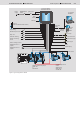
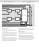
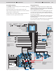
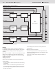

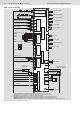
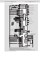
Table Of Contents

14/16 Bosch Rexroth AG Mobile Hydraulics
Dual Path Control DPC
RE 95 325/03.04
EMERGENCY
STOP
Output
ON
Speed of hydraulic motor left
Speed of hydraulic motor right
Tamper (option)
Vibration (option)
Steering potentiometer
GP200
Speed
limitation
Version II HG120GB
Version I
HG104GB
Speed
Steering sensor
Sensor mounting position
Left/Right
Version II
HG120GB
Forwards
Backwards
Forwards Version I
Backwards Version I
Slip steering
Work/travel mode
Automatic steering
Stop/Go
CAN
bus
only for
prototypes
Diagnostics plug for
BB-3 or BODEM
Speed display
Speed meter
Hydraulic motor V
g min
Brake control
Error lamp
Error lamp right
Error lamp left
Pump right backwards
Pump right forwards
Pump left backwards
Pump left forwards
RC6-9/20
Ignition lock with
starter non-repeat unit
Power supply
for electronics
Power
input
Supply for
power outputs
Proportional outputs
Switch outputs
Frequency inputs
Voltage inputs
Current inputs
Voltage inputs
Switch inputs
Ground
Ground connection,
Housing
Stabilized voltage source
5 V / 2x100 mA
Stabilized voltage source
5 V / 2x100 mA
CONT.
1)
Short, low-resistance connection from a housing screw to the unit or vehicle ground
2)
Separate ground connection from solenoid return lead to battery (chassis also possible)
3)
Separate fuses recommended for switches, sensors and electronics
4)
CAN bus: terminating resistor 120 Ω recommended (see installation instructions in REE 90 300-01)
5)
Separate ground connection possible from current source to battery, controller GND (pin 38/49)
6)
Stabilized voltage source
7)
Observe maximum current consumption where proportional solenoids and switch outputs are controlled simultaneously
Figure 8: Inputs and outputs on the DPCB control unit
DPCB Connection Diagram
Speed