
User Manual
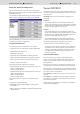

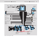
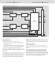
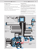
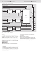

Table Of Contents

12/16 Bosch Rexroth AG Mobile Hydraulics
Dual Path Control DPC
RE 95 325/03.04
Figure 7: Dual path control DPCC: How it works
Display
For variant C, a display can be connected for calibration of
the dual path control system and for diagnostics. The process
variables and error messages are sent to the display via the
CAN bus.
Either DI2/11 or OPUS+ can be used for the display. The used
display must be selected in the parameters. Rexroth recom
-
mends use of the DI2/11 display, since it is more user-friendly
and has more functions.
Safety functions
Various options are available for monitoring travel behavior:
• Start condition
The start condition is used to prevent the drive from starting
unintentionally.
After the control unit is switched on (ignition switch turned
on), the lever (the direction switches) must be in the neutral
position and slip steering must be switched off in order for
the drive to be started.
To acknowledge faults, the lever must be placed in the
neutral position.
• Monitoring of inputs and outputs
The wires of the proportional solenoid outputs and of the
steering and speed potentiometers are monitored for cable
breaks and short circuit.
In the event of a fault, only the safety critical parts are
switched off.
EMERGENCY STOP (also switches RC off)
Actual speed of left motor
Actual speed of right motor
Stop / Go
Drive setpoint
Max. velocity
Steering setpoint
Slip steering
Transport mode / work mode
Setpoints for
additional functions
Additional function On/Off
Setpoint
preparation
Setpoint
preparation
Time ramps
Steering behavior
Speed
and
steering regulator
E
M
E
R
G
E
N
C
Y
S
T
O
P
Pump
Left
Pump
Right
Brake
Motor
Left/Right
Setpoint
preparation
Time ramps
Time ramps
Additional
pump 1
Additional
pump 2