
User Manual
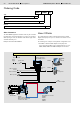
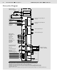
Table Of Contents

4/6 Bosch Rexroth AG Mobile Hydraulics
CEMA CAN Expansion Module RE 95 340/11.04
Connection Diagram
Ignition lock with
starter non-repeat unit
Power supply
for electronics
Power
input
Supply for
power outputs
Proportional
outputs
Switch
outputs
Frequency inputs
Sensor supply
voltage
Voltage inputsCurrent inputsSwitch inputs
Ground
Frequency input
FRQ_A1 or
switch input
DIG_FA1
Voltage output
ANA_A1V current
monitoring
Analog input
ANA_A1
Proportional output PWM_A1/
DIGP_A1
Switch output DIGL_A1
Switch input DIG_A1 or
frequency input FRQ_DA1
Diagnostics socket
for BB-3 or BODEM
CAN bus
4)
Ground connection
Housing
Inter-
face 1
reserved
Inter-
face 2
Frequency input
FRQ_A2 or
switch input
DIG_FA2
Voltage output
ANA_A2V current
monitoring
Analog input
ANA_A2
Switch input DIG_A5
Analog current input
ANA_A1I
Switch input DIG_A6
Analog current input
ANA_A2I
DIG_A2 / ANA_DA2
DIG_A3 / ANA_DA3
DIG_A4
Switch output DIGL_A2
Proportional output PWM_A2/
DIGP_A2
1)
Short, low-resistance connection from a housing screw to the unit or vehicle ground
2)
Separate ground connection from solenoid return lead to battery (chassis also possible)
3)
Separate fuses recommended for switches, sensors and electronics
4)
CAN bus: Terminating resistor 120 Ω recommended (see RDE 90 300-01 installation instructions)
5)
Separate ground connection from current source to battery, control unit GND (pin 38/49) possible
6)
Constant voltage source
7)
Observe max. current consumption where proportional solenoids and switch outputs are controlled simultaneously