
Specifications


+
-
Error
Amplifier
INTERNAL
LOOP
COMPENSATION
CONTROL
LOGIC
GATE
DRIVE
CIRCUITS
M4
M3
M5
VCON
FB
M2
M1
1.7A
+
-
Input Overcurrent
Protection
PGND
VOUT
SW2
SW1
EN
M6_g
M6
M6_g
SMALL
FET
LARGE
FET
PVIN
To
Analog Supply
SGND
One
Shot
Timer
Ref
+
-
FB
Network
PFM
Comparator
CLK
PWM RAMP
PVIN
LM3269
www.ti.com
SNVS793D –NOVEMBER 2011–REVISED MAY 2015
7 Detailed Description
7.1 Overview
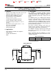
The LM3269 buck-boost converter provides high-efficiency, low-noise power for RF power amplifiers (PAs) in
mobile phones, portable communicators, and similar battery-powered RF devices. It is designed to allow the RF
PA to operate at maximum efficiency for a wide range of power levels from a single Li-Ion battery cell. The
capability of the LM3269 to provide an output voltage lower than, as well as higher than, the input battery voltage
enables the PA to operate with high linearity for a wide range of battery voltages, thereby extending the usable
voltage range of the battery. The converter feedback loop is internally compensated for both buck and boost
operation, and the architecture is such that it provides seamless transition between buck and boost modes of
operation. The LM3269 operates in energy saving Pulse Frequency Modulation (PFM) mode for increased
efficiencies and current savings during low-power RF transmission modes. The output voltage is dynamically
programmable from 0.6 V to 4.2 V by adjusting the voltage on the control pin VCON without the need for external
feedback resistors. The fast output voltage transient response of the LM3269 makes it suitable for adaptively
adjusting the PA supply voltage depending on its transmitting power, which prolongs battery life.
Additional features include current overload protection, output overvoltage clamp, and thermal overload
shutdown.
The LM3269 is constructed using a chip-scale 12-bump DSBGA package that offers the smallest possible size
for space-critical applications such as cell phones, where board area is an important design consideration. Use of
high switching frequency (2.4 MHz, typical) reduces the size of external components. As shown in the Typical
Application Circuit, only three external power components are required for circuit operation. Use of DSBGA
package requires special design considerations for implementation. (See DSBGA Package Assembly And Use)
Its fine bump-pitch requires careful board design and precision assembly equipment. Use of this package is best
suited for opaque-case applications where its edges are not subjected to high-intensity ambient red or infrared
light. In addition, the system controller should set EN low during power-up and other low supply voltage
conditions. (See Enable And Shutdown Mode.)
7.2 Functional Block Diagram
Copyright © 2011–2015, Texas Instruments Incorporated Submit Documentation Feedback 9
Product Folder Links: LM3269