
Specifications


2. 2 µH
PVIN
PV
IN
EN
SGND PGND
LM3269
V
OUT
FB
VCON
3G/4G
RF PA
-+
DAC
RFIC/BB
RF GND
RF GND
L1
PA Decoupling Caps
L2
V
IN
: 2.7 V to 5.5 V
V
OUT
: 0.6 V to 4.2 V
0.1 µF
C4
4.7 µF
C4
SW2SW1
0.1 µF
C4
10 µF
C4
LM3269
SNVS793D –NOVEMBER 2011 –REVISED MAY 2015
www.ti.com
Layout Guidelines (continued)
10.1.1.2 Manufacturing Considerations
The LM3269 package employs a 12-bump (4 x 3) array of 300 micron solder balls, with a 0.5 mm pad pitch. A
few simple design rules will go a long way toward ensuring a good layout.
• Pad size should be 0.265 ± 0.02 mm. Solder mask opening should be 0.375 ± 0.02 mm.
• As a thermal relief, connect to each pad with 9.5 mil wide, 5 mil long traces and incrementally increase each
trace to its optimal width. Symmetry is important to ensure the solder bumps re-flow evenly. Refer to TI
Application Note AN-1112 DSBGA Wafer Level Chip Scale Package (SNVA009).
10.1.1.3 LM3269 RF Evaluation Board
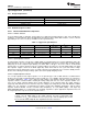
Figure 16. Simplified LM3269 RF Evaluation Board Schematic
1. Input Capacitor C2 should be placed closer to LM3269 than C1.
2. It is optional to add 100 nF (C1) on input of LM3269 for high frequency filtering.
3. Bulk Output Capacitor C3 should be placed closer to LM3269 than C4.
4. It is optional to add 100 nF (C4) on output of LM3269 for high frequency filtering.
5. Connect both GND terminals of C1 and C4 directly to System RF GND layer of phone board.
6. Connect bumps SGND (C2) directly to System GND.
7. TI has seen improvement in high frequency filtering for small bypass capacitors (C1 and C4) when they are
connected to System GND instead of same ground as PGND. These capacitors should be 0201 (0603
metric) case size for minimum footprint and best high frequency characteristics.
8. A ferrite bead (L2) may help to improve high frequency noise.
Table 4. Recommended Components
DESIGNATOR PART NUMBER VALUE CASE SIZE VENDOR
C1* GMR033R60J104KE19D 0.1 µF 0201 (0603 metric) Murata
C2 C1608X5R0J106 10 µF 0603 (1608 metric) TDK
C3 C1608X5RR0J475M 4.7 µF 0603 (1608 metric) TDK
C4* GRM033R60J104KE19D 0.1 µF 0201 (0603 metric) Murata
L1 MIPSZ2520D2R2 2.2 µH 1008 (2520 metric) FDK
L2* BLM15AX100SN1 10 Ω 0402 (1005 metric) Murata
*Optional high frequency caps and high-frequency ferrit bead.
16 Submit Documentation Feedback Copyright © 2011–2015, Texas Instruments Incorporated
Product Folder Links: LM3269