8201 Modulation Analyzer Quick Start Guide PN: 98406800A Taking performance to a new peak
8201 Quick Start Guide Version 1.00 ( PN: 98406800A ) The 8201 is a versatile, precision, solid-state instrument with features and performance characteristics suitable for laboratory and industrial applications. It covers a frequency range of 100 kHz to 2.5 GHz. The 8201 modulation analyzer is easy and convenient to use.
Content Safety and Caution summary......................................................................................... 4 Limited Warranty.............................................................................................................. 4 Instrument Displays and Operating Controls.............................................................. 5 Getting Started..................................................................................................................
Safety and Caution Summary Limited Warranty The following general safety precautions must be observed during all Boonton Electronics warrants its products to the original purchaser phases of operation and maintenance of the Boonton 8201 Modu- to be free from defects in material and workmanship and to operate lation Analyzer.
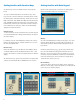
Instrument Displays & Operating Controls Getting Started The 8201 instrument displays are shown as below in Figure-1. The The following instructions walk through a basic operation and func- front panel of the Model 8201 is organized for simple instrument tionality tests to verify that the unit is working properly. operation. It consists of a display window and a separate keyboard area. The display area contains the carrier FREQUENCY/LEVEL display, 1. Turn ON the instrument and press LCL (INIT) key.
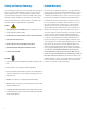
1 30 8 6 7 2 9 10 11 13 14 15 16 3 12 25 17 18 19 26 27 28 22 4 20 31 21 29 5 32 23 24 Figure-2: Front View of 8201 Modulation Analyzer Table-1: Controls, Displays and Connectors of Front Panel of 8201 Modulation Analyzer (Fig-2) Control, Indicator Or Connector Index Number Function FREQUENCY/LEVEL display 1 Displays carrier frequency in kHz or MHz, and RF level in dBm or mV. Alternately displays error codes and messages.
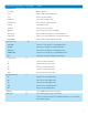
Control, Indicator Or Connector Index Number DATA ENTRY keys: 9 Function 0 – 9 keys Number entry keys. . key Select decimal point during data entry. - key Prefix for negative quantity. V/GHz key Selects volts or gigahertz units. mV/MHz key Selects millivolts or megahertz units. kHz key Selects kilohertz units. %Hz key Selects percent or Hertz units. dBm key Selects decibels referenced to 1 milliwatt. DEL(↑) key Deletes the last entered digit, or increments parameter.
Control, Indicator Or Connector Index Number Function DIST key 15 Selects audio distortion measurement. RATIO key 16 Alternate action key. Changes the active display from absolute to relative. Units keys may be used to select displayed units. AM key 17 Selects AM modulation as the active function. Use before setting AM modulation reference for subsequent ratio measurement, or to activate the AM modulation display. FM key 18 Selects FM modulation as the active function.
2 3 1 4 10 5 12 6 8 11 13 7 9 Figure-3: Rear View of 8201 Modulation Analyzer Table-2: Controls, Displays and Connectors of Back Panel of 8201 Modulation Analyzer (Figure-3) Control, Indicator or Connector Index Number Function Fuse holder 1 Holds fuse for ac line protection. Line connector 2 Permits connection of instrument to ac power supply. Voltage Selector Switch 3 Permits the selection of various ac power supply voltages.
Getting familiar with Function Keys Getting familiar with Data Keypad The function keys of 8201 modulation analyzer are described as Operation of the data keypad is conventional. The data keypads of below: the 8201 Modulation Analyzer are described as below: The top row of illuminated switches are the function keys. These keys are used to select the parameter to be displayed and to enable the data keypad for subsequent data entry.
kHz and GHz Keys The kHz and GHz keys are provided for convenience when entering frequency; however, the display will only indicate in MHz. Similarly, the V key can be used for entering input level; however, the display will indicate in millivolts. ENTER key Figure-6: Measurement Control Keys of 8201 Modulation Analyzer The ENTER key is used for unitless quantities, such as special function and program numbers.
OPTIONAL Filter Keys Other Keys The ALT key is active if optional filters are installed in the Model 8201. Optional filters available are: THRU Permits connection of external filters in the audio path CCIR CCIR recommendation 468-3 bandpass filter CCITT CCITT recommendation P.
Displayed Messages SPCL 1-4 (MODULATION RANGE SETTINGS) SPCL functions 1 through 4 permit the operator to select the modula- UNLOC message tion display range. This is useful for speeding up measurements When the Model 8201 unlocks, the FREQUENCY/LEVEL display will be where modulation may be removed temporarily, or in situations overwritten with the ‘UNLOC’ message and the AUDIO and MODU- where the modulation range is known.
Calibration and Performance Tests The internal calibrators of the 8201 Modulation Analyzer provide modulation standards for AM, FM and PM measurements. They are activated by the operator as required by the measurement. Specifications AM 0.1% accuracy FM 0.1% accuracy PM 1.0% accuracy FM Calibration The calibration process consists of: 1. Applying to the FM discriminator , in alternation, two accurately controlled frequencies 2. Measuring the resulting recovered modulation information 3.