
Operating instructions


08/06 61
5.3 Frequency and percentage reference channel
T
he varied functions for the specification of the reference values are connected in the
various configurations by the frequency or percentage reference channel. The
Refer-
ence frequency source
475, and the Reference percentage source 476 determine the
additive connection of the available reference sources as a function of the installed
hardware.
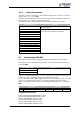
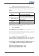
Operation mode Function
2 -EM-S1INA, absolute value Reference source is the analog input EM-S1INA
4 -
MFI1A + EM-S1INA, abso-
lute value
Reference sources are the multifunctional input
MFI1A and the analog input EM-S1INA
14 -
MFI1A + EM-S1INA + FF,
absolute value
Reference sources are the multifunctional input
MFI1A, analog input EM-S1INA and fixed frequency
FF
24 -
MFI1A + EM-S1INA + MP,
absolute value
Reference sources are the multifunctional input
MFI1A, analog input EM-S1INA and the motor poten-
tiometer function MP
34 -
speed sensor 2 (F2), abso-
lute value
The frequency signals of the resolver are evaluated
using a fixed number of division marks of 1024 as a
reference value.
102 to 124 Operation modes with signs (+/-)
Additional to the operation modes listed, those stated in the operatin
g
instructions o
f
the frequency inverter in the chapter "Frequency reference channel“, and in the chap-
ter "Percentage reference channel“ also apply.
5.4 Actual value display
The actual value of speed sensor 2 can be read via the parameters Frequency
s
pee
d
sensor 2 219 and Speed, speed sensor 2 220.
The analog input signal on analog input EM-S1INA can be a volta
g
e or a current si
g
nal
depending on the setting of switch S3. Accordingly, the actual value parameter
Analo
g
input EM-S1INA 253 is displayed as a percentage.
5.5 Repetition frequency output EM-RFOUT
The repetition frequency output EM-RFOUT emulates a speed sensor. The repetition
frequency output delivers the frequency signal of the resolver as a simulation of an
incremental speed sensor with reference si
g
nal. The number of division marks is se
t
permanently to 1024 division marks, thus no parameterization is required.
For parameter
Repetition Freq. Operation 555 the additional operation mode 4 – Fre-
quency speed sensor 2 is selectable. It can put out the absolute value of
F
requency
speed sensor 2
219 to the multifunctional output MFO1 of the frequency inverter.
Assignment of the outputs:
Repetition frequency output EM-RFOUT (X410A.7): track A+
Repetition frequency output EM-RFOUT (X410B.1): track A-
Repetition frequency output EM-RFOUT (X410B.2): track B+
Repetition frequency output EM-RFOUT (X410B.3): track B-