
Operating instructions

12 08/06
4.2 Cables
For the bus line, use twisted cable with harness shield (no foil shield).
Attention! The control and communication lines are to be laid physically separate
from the power lines. The harness screen of the data lines is to be con-
nected to ground (PE) on both sides on a large area and with good con-
ductivity.
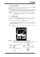
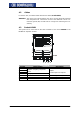
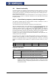
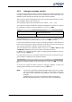
4.3 Socket X410B
The system bus is connected via the three terminals of the socket X410B on the
EM-RES-01 expansion module.
X410A
X
410B
1
2
4
3
5
6
7
1
2
4
3
5
6
7
X
410B
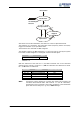
Socket X410B
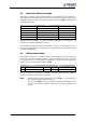
Socket Input/Output Description
X410B.1
X410B.2
X410B.3
Repetition frequency output EM-
RFOUT
X410B.4 Analog input EM-S1INA
Chapter
"Control inputs and outputs“
X410B.5 CAN-Low CAN-Low (System bus)
X410B.6 CAN-High CAN-High (System bus)
X410B.7 GND CAN-GND (System bus)