
Operating instructions

08/06 11
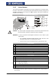
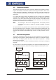
4 System bus interface
The CAN connection of the system bus is physically designed according to ISO-DIS
11898 (CAN High Speed). The bus topology is the line structure.
In the default version, the frequency inverter support a CAN protocol controller, which
may exist in either the CM-CAN communication module with CANopen interface OR in
an expansion module for the system bus, such as the EM-RES-01 expansion module.
Attention! Installation of two optional components with CAN-Protocol controller re-
sults in a deactivation of the system bus interface in the EM-RES-01 ex-
pansion module.
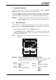
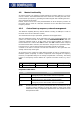
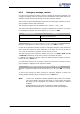
4.1 Bus termination
The necessary bus terminator at the physically first and last subscriber can alternativel
y
be activated via the two DIP switches S1 and S2 on the EM-RES-01 expansion mod-
ule.
• Either set S1 to ON and S2 to OFF for a passive termination,
• or set S1 and S2 to ON for an active termination. This results in an improved ed
g
e
shape of the CAN signals, which results in an improvement of the signal shapes, in
particular in extended systems.
Note: Switch S3 is used to confi
g
ure the analo
g
input (see chapter "Analo
g
inpu
t
EM-S1INA“).
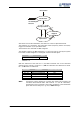
X410A
X
410B
S1
S2
S3
Attention! The factory setting for the bus termination is OFF.
An active termination may only be switched once on a bus system via S1
and S2. The other bus termination has to be done in passive mode.
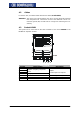
CAN high (X410B.6)
120
Ω
CAN low (X410B.5)
Data line
Data line
CAN high (X410B.6)
332
Ω
CAN low (X410B.5)
Data line
Data line
passive active
332
Ω