INDUSTRY PROCESS AND AUTOMATION SOLUTIONS Expansion Module EM-RES-01 Frequency Inverter 230 V / 400 V ACTIVE and ACTIVE Cube GB
General points on the documentation The present supplement of the documentation is valid for the frequency inverter series ACT and ACU. The information necessary for the assembly and application of the EM-RES-01 expansion module is documented in this guidance. For better clarity, the user documentation is structured according to the customerspecific demands made of the frequency inverter.
TABLE OF CONTENTS 1 General safety and application information .................................................................. 4 1.1 General information................................................................................................. 4 1.2 Proper use................................................................................................................ 4 1.3 Transport and storage .............................................................................................
TABLE OF CONTENTS 4.11 Process data channels, PDO ............................................................................... 30 4.11.1 Identifier assignment process data channel.............................................................. 30 4.11.2 Operation modes process data channel.................................................................... 31 4.11.3 Timeout monitoring process data channel ................................................................ 32 4.11.
1 General safety and application information This documentation has been created with greatest care and has been extensively and repeatedly checked. For reasons of clarity, we have not been able to take all detailed information on all the types of the products and also not every imaginable case of positioning, operation or maintenance into account.
1.3 Transport and storage Transport and storage are to be done appropriate in the original packing. Store the units only in dry rooms, which are protected against dust and moisture and are subjected to little temperature deviations only. Observe the climatic conditions according to standard EN 50178 and to the information on the label of the original packing. The duration of storage without connection to the admissible reference voltage may not exceed one year. 1.
2 Introduction This document describes the possibilities and the properties of the EM-RES-01 expansion module for the frequency inverters of the ACT and ACU device series. Note: This document exclusively describes the EM-RES-01 expansion module. It does not provide basic information on the operation of the ACT and ACU series frequency inverters. The EM-RES-01 expansion module is an optional hardware component to extend the functionality of the frequency inverter.
3 Installation of the EM-RES-01 expansion module 3.1 General The mechanical and electrical installation of the EM-RES-01 expansion module is to be carried out by qualified personnel according to the general and regional safety and installation directives. Safe operation of the frequency inverter requires that the documentation and the device specification be complied with in installation and start of operation.
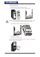
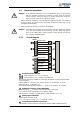
The EM-RES-01 expansion module is supplied in a housing for assembly on the lower slot of the frequency inverter. • Remove the lower cover (1) of the frequency inverter. The slot for the EM-RES-01 expansion module becomes accessible. 1 Caution! • The EM-RES-01 expansion module (2) is pre-fitted in a housing. Do NOT touch the PCB visible on the back, as modules may be damaged. Plug the EM-RES-01 expansion module (2) onto the slot (3). 2 3 • Re-install the lower cover (1).
3.3 Danger! Electrical installation If the following instructions are not complied with, there is direct danger with the possible consequences of death or severe injury by electrical current. Further, failure to comply can lead to destruction of the frequency inverter and/or of the expansion module. • Before electrical installation of the EM-RES-01 expansion module, the frequency inverter must be de-energized. Take appropriate measures to make sure it is not energized unintentionally.
3.3.2 Control Sockets The control and software functionality can be freely configured for economical operation with a safe function. The operating instructions describe the factory setting of the standard connections in the Configuration 30 in question and also the software parameters for the setting. Expansion module EM-RES-01 Wieland DST85 / RM3,5 0.14 … 1.5 mm2 AWG 30 … 16 2 0.14 … 1.5 mm AWG 30 … 16 0.25 … 1.0 mm2 AWG 22 … 18 2 0.25 … 0.75 mm AWG 22 … 20 0.2 … 0.3 Nm 1.8 … 2.
4 System bus interface The CAN connection of the system bus is physically designed according to ISO-DIS 11898 (CAN High Speed). The bus topology is the line structure. In the default version, the frequency inverter support a CAN protocol controller, which may exist in either the CM-CAN communication module with CANopen interface OR in an expansion module for the system bus, such as the EM-RES-01 expansion module. Attention! 4.
4.2 Cables For the bus line, use twisted cable with harness shield (no foil shield). Attention! The control and communication lines are to be laid physically separate from the power lines. The harness screen of the data lines is to be connected to ground (PE) on both sides on a large area and with good conductivity. 4.3 Socket X410B The system bus is connected via the three terminals of the socket X410B on the EM-RES-01 expansion module. X410A X410B 1 Socket X410B.1 X410B.2 X410B.3 X410B.4 X410B.
4.4 Baud rate setting/line length The setting of the baud rate must be identical in all subscribers on the system bus. The maximum possible baud rate is based on the necessary overall line length of the system bus. The baud rate is set via the parameter Baud-Rate 903 and thus defines the possible line length.
4.6 Functional overview The system bus produces the physical connection between the frequency inverters. Logical communication channels are produced via this physical medium. These channels are defined via the identifiers. As CAN does not possess a subscriber-oriented, but a message-oriented addressing via the identifiers, the logical channels can be displayed via it. In the basic state (factory setting) the identifiers are set according to the Predefined Connection Set of CANopen.
4.7.1 SDO channels (parameter data) Each frequency inverter possesses two SDO channels for the exchange of parameter data. In a slave device, these are two server SDO's, in a device defined as a master a client SDO and a server SDO. Attention must be paid to the fact that only one master for each SDO channel may exist in a system. Note: Only one master can initiate by the system bus an exchange of data via its client SDO.
4.8 Master functionality An external control or an frequency inverter defined as a master (node ID = 0) can be used as a master. The fundamental tasks of the master are controlling the start of the network (boot-up sequence), generating the SYNC telegram and evaluating the emergency messages of the slaves. Further, there can be access to the parameterization of all the frequency inverters on the system bus by means of a field bus connection via the client SDO of the master frequency inverter. 4.8.
Einschalten (1) Initialisation aus beliebigem Zustand (2) Pre-Operational (4) (7) (5) Stopped (3) (6) (8) Operational After Power On and the initialization, the slaves are in the Pre-Operational state. The transition (2) is automatic. The system bus master (frequency inverter or PLC/PC) triggers the transition (3) to Operational state. The transitions are controlled via NMT telegrams. The identifier used for the NMT telegrams is "0" and may only be used by the system bus master for NMT telegrams.
4.8.2 SYNC telegram, generation If synchronous PDO’s have been created on the system bus, the master must send the SYNC telegram cyclically. If an frequency inverter has been defined as a system bus master, the latter must generate the SYNC telegram. The interval for the SYNC telegram of an frequency inverter defined as the system bus master is adjustable. The SYNC telegram is a telegram without data. The default identifier = 128 according to the Predefined Connection Set.
4.8.3 Emergency message, reaction If a slave on the system bus suffers a fault, it transmits the emergency telegram. The emergency telegram marks the node ID for the identification of the failed node via its identifier and the existing fault message via its data contents (8 bytes). After a fault has been acknowledged on the slave, the latter again transmits an emergency telegram with the data content zero. The emergency telegram has the identifier 128 + node ID ( = 129 ...
4.8.4 Client SDO (system bus master) Each subscriber on the system bus can be addressed via the SDO channels. In this way, each subscriber can be addressed and parameterized by one master via its client SDO1. All the parameters of the data types uint/int/long are accessible. String parameters can not be processed.
4.9 Slave functionality 4.9.1 Implement boot-up sequence, network management 4.9.1.1 Boot-up message After the initialization, each slave on the system bus transmits its boot-up message (heartbeat message). Note: The boot-up telegram has the identifier 1792 + node ID and a data byte with contents = 0x00. This telegram is of importance if a PLC/PC with CANopen functionality is used as a master. An frequency inverter defined as a system bus master does not evaluate the boot-up message. 4.9.1.
4.9.2 Process SYNC telegram If synchronous PDO’s have been created in an frequency inverter, their processing is synchronized with the SYNC telegram. The SYNC telegram is generated by the system bus master and is a telegram without data. The identifier is 128 according to the Predefined Connection Set. If a PC or PLC is used as a master, the identifier of the SYNC telegrams can be adapted by parameterization on the frequency inverter.
4.9.3 Emergency message, fault switch-off As soon as a fault switch-off occurs in a slave frequency inverter, the emergency telegram is transmitted. The emergency telegram marks the node ID for the identification of the failed node via its identifier and the existing fault message via its data contents (8 bytes). The emergency telegram has the identifier 128 + node ID. After a fault acknowledgment, another emergency telegram is transmitted, with the data content (Byte 0 ...7) being set to "0" this time.
4.9.4 Server SDO1/SDO2 The communication channel for the exchange of parameter data is the SDO channel. Communication works according to the client/server model. The server is the subscriber holding the data (here the frequency inverter), the client the subscriber requesting or wanting to alter the data (PLC, PC or frequency inverter as system bus master). For the frequency inverter, two server SDO channels have been implemented.
If a PC or a PLC is used as a master, the identifiers of the Rx/Tx-SDO1 can be adapted by parameterization on the frequency inverter. Attention! In free assignment of identifiers, there may not be any double occupancy. The identifier range 129...191 may not be used as the emergency telegrams can be found there. The setting of the identifiers of the RxSDO1 is done via the parameter RxSDO1- Identifier 921. Parameter No. Description 921 RxSDO1-Identifier Min. 0 Setting Max. 2047 Fact. sett.
4.10 Communication channels, SDO1/SDO2 4.10.1 SDO telegrams (SDO1/SDO2) The service used for the exchange of parameter data is SDO Segment Protocol Expedited. The data (type uint, int, long) are exchanged in a telegram. Access to the parameters in the frequency inverters with a statement of parameter number and data set is displayed via the addressing defined for object access pursuant to the specifications of CANopen via Index/Sub-Index. Index = parameter number / Sub index = data set.
Reading parameters: Client Î Server 0 Ctrl. byte 0x40 SDO Upload (expedited) 1 2 Parameter number LSB MSB Server Î Client 0 Ctrl. byte 0x42 uint/int long 4 5 6 7 6 7 0x00 ... MSB 0x00 MSB 6 7 0 0 Data 0 Upload Response Î Reading process free of errors 1 2 Parameter number LSB MSB Server Î Client 0 Ctrl. byte 0x80 3 Data set 0xnn 3 Data set 0xnn 4 5 Data LSB LSB LSB MSB ...
4.10.2 Communication via field bus connection (SDO1) If an frequency inverter has been defined as the system bus master and equipped with a field bus interface, access to the parameterization of all the subscribers in existence on the system bus is possible by means of this field bus interface via the first SDO channel (SDO1). An extension has been created in the protocol frame of the field buses for this purpose.
Display of node ID system bus in the VECTRON bus protocol: System bus Node-ID System bus (ASCII-) HEX value System bus address character address 1 A 41 31 2 B 42 32 3 C 43 33 4 D 44 34 5 E 45 35 6 F 46 36 7 G 47 37 8 H 48 38 9 I 49 39 10 J 4A 40 11 K 4B 41 12 L 4C 42 13 M 4D 43 14 N 4E 44 15 O 4F 45 16 P 50 46 17 Q 51 47 18 R 52 48 19 S 53 49 20 T 54 50 21 U 55 51 22 V 56 52 23 W 57 53 24 X 58 54 25 Y 59 55 26 Z 5A 56 27 [ 5B 57 28 \ 5C 58 29 ] 5D 59 30 ^ 5E 60 61 62 63 08/06 (ASCII-) character _ ` a b c
4.11 Process data channels, PDO 4.11.1 Identifier assignment process data channel The process channel for the exchange of process data under CANopen is the PDO channel. Up to three PDO channels with differing properties can be used in one device. The PDO channels are defined via identifiers according to the Predefined Connection Set to CANopen: Identifier 1. Rx-PDO = Identifier 1. Tx-PDO = 512 + Node-ID 384 + Node-ID Identifier 2. Rx-PDO = Identifier 2.
4.11.2 Operation modes process data channel The transmit/receive behavior can be time controlled or controlled via a SYNC telegram. The behavior can be parameterized for each PDO channel. Tx-PDO’s can work time controlled or SYNC controlled. A time controlled TxPDO transmits its data at the interval of time set. A SYNC controlled TxPDO transmits its data after the arrival of a SYNC telegram. RxPDO’s in the time controlled setting forward the received data to the application immediately.
4.11.3 Timeout monitoring process data channel Each frequency inverter monitors its received data for whether they are updated within a defined time window. The monitoring is done onto the SYNC telegram and the RxPDO channels. Monitoring SYNC / RxPDO‘s No. 939 941 942 945 Parameter Description SYNC Timeout RxPDO1 Timeout RxPDO2 Timeout RxPDO3 Timeout Min. 0 ms 0 ms 0 ms 0 ms Setting Max. 60000 ms 60000 ms 60000 ms 60000 ms Fact. sett. 0 ms 0 ms 0 ms 0 ms Setting "0" means no timeout monitoring.
4.11.4 Communication relationships of the process data channel Regardless of the process data to be transmitted, the communication relationships of the process data channels must be defined. The connection of PDO channels is done via the assignment of the identifiers. The identifiers of Rx-/Tx-PDO must match in each case.
4.11.5 Virtual links A PDO telegram contains 0 ...8 data bytes according to CANopen. A mapping for any kind of objects can be done in these data bytes. For the system bus, the PDO telegrams are firmly defined with 8 data bytes. The mapping is not done via mapping parameters as with CANopen, but via the method of sources and links. Each function provides its output data via a source. These sources are defined via source numbers. The input data of functions are defined via parameters.
For the system bus, the input data of the TxPDO’s are also displayed as input parameters and the output data of the RxPDO’s as sources. Example 2: Function A Inverter 1 Source-No. 27 TxPDO Inverter 1 Parameter 977 system bus Function B Inverter 1 Source-No. 5 RxPDO Inverter 2 Parameter 972 Function C Inverter 2 Source-No. 727 Parameter 125 Source-No. 724 Parameter 187 system bus Example 2 displays the same situation as Example 1.
The virtual links with the possible sources are related to the Rx/TxPDO channels. For this purpose, the eight bytes of the Rx-/TxPDO’s are defined structured as inputs and sources. This exists for each of the three PDO channels.
4.11.5.1 Input parameters of the TxPDO’s for data to be transmitted The listed parameters can be used to stipulate the data that are to be transported there for each position in the TxPDO telegrams. The setting is done in such a way that a source number is entered for the required data in the parameters. TxPDO1 Byte 0 1 2 3 4 5 6 7 TxPDO2 Byte 0 1 2 3 4 5 6 7 TxPDO3 Byte 0 1 2 3 4 5 6 7 Note: 08/06 P. No. Boolean input 946 Boolean1 947 Boolean2 948 Boolean3 949 Boolean4 P. No.
With this method, there are up to three possibilities for a meaning of the contents of the individual bytes. Each byte may only be used for one possibility. To ensure this, the processing of the input links is derived from the setting. If an input link has been set to the fixed value of zero, it is not processed. The settings for the fixed value zero are: Source = Source = 7 (FALSE) 9 (0) for Boolean variables for uint, int, long variables This is simultaneously the factory setting.
4.11.5.2 Source numbers of the RxPDO’s for received data Equivalent to the input links of the TxPDO’s, the received data of the RxPDO’s are displayed via sources or source numbers. The sources existing in this way can be used in the frequency inverter via the local input links for the data targets. RxPDO1 Byte 0 1 2 3 4 5 6 7 RxPDO2 Byte 0 1 2 3 4 5 6 7 RxPDO3 Byte 0 1 2 3 4 5 6 7 Source No. Boolean value 700 Boolean1 701 Boolean2 702 Boolean3 703 Boolean4 Source No.
4.11.5.3 Examples of virtual links Example 1: Frequency inverter 1 Source Input link TxPDO1 - No. Byte Control word 950 0 740 1 Output reference frequency channel 62 Frequency inverter 2 RxPDO1 Source Target Byte - No. 0 704 Control input, Control word 1 99 2 3 4 709 Ramp input, Line set value 5 137 6 7 2 3 4 5 6 7 955 Parameter 950 = Source-No. 740 Parameter 955 = Source-No. 62 Parameter 99 = Source-No. 704 Parameter 137 = Source-No.
4.12 Control parameters For the monitoring of the system bus and the display of the internal states, two control parameters are provided. There is a report of the system bus state and a report of the CAN state via two actual value parameters. The parameter Node-State 978 gives information about the Pre-Operational, Operational, Stopped state. A PDO transfer is only possible in the Operational state. The state is controlled by the system bus master (PLC / PC / frequency inverter) via NMT telegrams.
4.13 Handling of the parameters of the system bus As soon as the system bus expansion module EM-SYS exists in an frequency inverter, the actual value parameters for system state and bus state are activated and can be observed in the actual value menu VAL of the control unit KP500 or with the VPlus PC program in the menu Actual values \ Systembus. Note: The actual value parameters are on control level 3 and are thus available for the user at any time.
TxPDO-Function 930TxPDO1 931TxPDO1 932TxPDO2 933TxPDO2 934TxPDO3 935TxPDO3 RxPDO-Function 936RxPDO1 Function 937RxPDO2 Function 938RxPDO3 Function Timeout 939SYNC Timeout 941RxPDO1 Timeout 942RxPDO2 Timeout 945RxPDO3 Timeout TxPDO1 Objects 946TxPDO1 947TxPDO1 948TxPDO1 949TxPDO1 950TxPDO1 951TxPDO1 952TxPDO1 953TxPDO1 954TxPDO1 955TxPDO1 Boolean1 Boolean2 Boolean3 Boolean4 Word1 Word2 Word3 Word4 Long1 Long2 TxPDO2 Objects 956TxPDO2 957TxPDO2 958TxPDO2 959TxPDO2 960TxPDO2 961TxPDO2 962TxPDO2 963Tx
4.14 Utilities For the planning of the system bus according to the drive tasks in question, there are utilities in the form of tables. The planning of the system bus is done in three steps: 1. Definition of the communication relationships 2. Production of the virtual links 3. Capacity planning of the system bus The priority assignment of the identifiers is relevant for the definition of the communication relationships. Data that are to be transmitted with a higher priority must be given low identifiers.
08/06 PDO TxPDO1 RxPDO1 TxPDO2 RxPDO2 TxPDO3 RxPDO3 Identifier ________ Inverter: ________ Inverter: ________ Inverter: ________ PDO TxPDO1 RxPDO1 TxPDO2 RxPDO2 TxPDO3 RxPDO3 Identifier PDO TxPDO1 RxPDO1 TxPDO2 RxPDO2 TxPDO3 RxPDO3 Identifier PDO TxPDO1 RxPDO1 TxPDO2 RxPDO2 TxPDO3 RxPDO3 Identifier PDO TxPDO1 RxPDO1 TxPDO2 RxPDO2 TxPDO3 RxPDO3 Identifier Node-ID: ________ Node-ID: ________ Node-ID: ________ Node-ID: ________ ________ Inverter: Node-ID: ________ Inverter: 4.14.
46 Source- Input Link/Parameter-No. No. Boolean uint/int TxPDO-No.: ________ long (Tx/RxPDO) Input Link/Parameter-No. Boolean uint/int RxPDO-No.: ________ ________ long SourceNo. Node-ID: Identifier: ___________ Node-ID: ________ Inverter: ___________________________ Inverter : ___________________________ 4.14.2 Production of the virtual links The virtual links are planned and documented with the help of the table. The table is available as a Microsoft Word document "vvk.
4.14.3 Capacity planning of the system bus Each PDO telegram possesses a constant useful data content of 8 Bytes. According to worst case, this results in a maximum telegram length of 140 bits. The maximum telegram run time of the PDO’s is thus stipulated via the set baud rate.
The capacity planning are planned and documented with the help of the table. The work sheet is available as a Microsoft Excel document "Load_Systembus.xls" on the BONFIGLIOLI VECTRON product CD or by request.
5 Control inputs and outputs 5.1 Analog input EM-S1INA 5.1.1 General The analog input of the EM-RES-01 expansion module can optionally be configured as a voltage or a current input.
5.1.3 Characteristic The mapping of the analog input signals onto a frequency or percentage reference value is possible for various demands. The parameterization is to be done via two points of the linear characteristic of the reference channel. The characteristic point 1, with the coordinates X1 and Y1, and the characteristic point 2, with the coordinates X2 and Y2, can be set in four parameters.
5.1.4 Operation modes The operation modes of the analog input characteristic enable application-related scaling as a supplement to the characteristic points stated. One of the four linear types of characteristic is selected for adaptation of the signal for the analog input signal via the parameter Operation mode 562. If the characteristic points are not suited for the type of characteristic selected, the characteristic points are corrected internally.
5.1.4.1 Examples The analog input signal is mapped onto a reference value as a function of the characteristic. The following examples show the operation modes for an analog voltage signal. The parameter Minimum Frequency 418 is set to the value 0.00 Hz. The characteristic point 100% for the Y-axis corresponds to the parameter Maximum Frequency 419 of 50.00 Hz in the examples. Attention! The various operation modes change the input characteristic as a function of the parameterized characteristic points.
Y 42.50Hz Characteristic point 1: X1 = 30.00 % · 10 V = 3.00 V (X2=80% / Y2=85%) Y1 = -50.00 % · 50.00 Hz = -25.00 Hz X 3.00V Characteristic point 2: X2 = 80.00 % · 10 V = 8.00 V Y2 = 85.00 % · 50.00 Hz = 42.50 Hz Tolerance band: ΔX = 2.00 % · 10 V = 0.20 V 8.00V -25.00Hz (X1=30% / Y1=-50%) The change of direction of rotation is done in the example at an analog input signal of 4.85 V, with a tolerance band of ±0.20 V.
Operation mode "101 – bipolar absolute value" The operation mode "101 – bipolar absolute value“ maps the bipolar analog signal onto a unipolar input characteristic. The formation of the absolute amount takes the characteristic into account comparable to the "bipolar" operation mode, but the characteristic points are reflected on the X-axis with a negative value for the Y-axis. Y 42.50Hz Characteristic point 1: X1 = -70.00% · 10 V = -7.00 V (X2=80% / Y2=85%) Y1 = -50.00% · 50.00 Hz = -25.00 Hz 25.
5.1.6 Tolerance band and hysteresis The analog input characteristic with change of sign of the reference value can be adapted by the parameter Tolerance band 560 of the application. The tolerance band to be defined extends the zero crossing of the speed relative to the analog control signal. The percentage parameter value is relative to the maximum current or voltage signal. Parameter No. Description 560 Tolerance band Min. 0.00 % Setting Max. 25.00 % (X2 / Y2) Fact. sett. 2.00 % (X2 / Y2) pos. max.
5.1.7 Error and warning behavior The monitoring of the analog input signal necessary according to the application is to be configured via the parameter Error/Warning behavior 563. Operation mode 0 -Off 1 -Warning < 1 V / 2 mA 2 -Shutdown < 1 V / 2 mA Fault switch-off 3< 1 V / 2 mA Function The input signal is not monitored. If the input signal is less than 1 V or 2 mA, there is a warning message.
5.1.9 Filter time constant The time constant of the filter for the reference analog value can be set via the parameter Filter time constant 561. The time constant states the time for which the input signal is averaged by means of a low pass filter, e.g. in order to eliminate fault effects. The setting range is a range of values between 0 ms and 5000 ms in 15 steps.
5.2.1 Offset In order to enable the start of a synchronous machine, the absolute position of the rotor must be known. This information is required in order to actuate the stator windings in the right order depending on the position of the rotor. The position of the rotary field in the synchronous machine must be controlled in order to obtain a continuous movement of the rotor.
• Turn motor shaft manually. Check the sense of rotation of the resolver via the actual value of parameter Frequency Speed Sensor 2 219. In the case of a clock-wise rotation of the motor shaft, positive values are displayed for the actual frequency value. If the displayed sense of rotation does not correspond to the actual sense of rotation, change the connections SIN+ and SIN- at socket X410A of the frequency inverter. The Offset 382 must be between 0° and 360°, divided by the number of motor pole pairs.
If the motor does not start despite the phase exchange: • increase the parameter value for Offset 382 by 90°, divided by the no. of motor pole pairs. If the motor still does not turn, exchange the two motor phases (e.g. U and V) again. − The motor turns and accelerates until it reaches the Frequency Switch-Off Limit 417: − • Check the resolver lines and check the resolver connection contacts.
5.3 Frequency and percentage reference channel The varied functions for the specification of the reference values are connected in the various configurations by the frequency or percentage reference channel. The Reference frequency source 475, and the Reference percentage source 476 determine the additive connection of the available reference sources as a function of the installed hardware.
6 Parameter list The parameter list is structured according to the menu branches of the control unit. For better clarity, the parameters are marked with pictograms: The parameter is available in the four data sets The parameter value is adjusted by the SETUP routine if a control method for a synchronous machine is selected for parameter Configuration 30. This parameter cannot be written in the operation of the frequency inverter 6.1 Actual value menu (VAL) Actual values of the machine No.
Systembus No.
7 Annex 7.1 Error messages The various control functions and methods and the hardware of the frequency inverter contain functions, which continuously monitor the application. As a supplement to the messages documented in these operating instructions, the following failure keys are activated by the EM-RES-01 expansion module. 21 Control connections Resolver synchronization not successful. Check resolver signal for interferences. 22 Resolver counting error: Check resolver signal for interferences.
Bonfiglioli Worldwide & BEST Partners AUSTRALIA BONFIGLIOLI TRANSMISSION (Aust) Pty Ltd. 48-50 Adderley St. (East) Auburn (Sydney) N.S.W. 2144 Tel. (+61) 2 8748 4400 - Fax (+61) 2 9748 8740 P.o. Box 6705 Silverwater NSW 1811 www.bonfiglioli.com.au - bta1@bonfiglioli.com.au HUNGARY AGISYS AGITATORS & TRANSMISSIONS Ltd 2045 Törökbálint, Tö u.2. Hungary Tel. +36 23 50 11 50 - Fax +36 23 50 11 59 www.agisys.hu - info@agisys.com AUSTRIA MOLL MOTOR GmbH Industriestrasse 8 - 2000 Stockerau Tel.
INDUSTRY PROCESS AND AUTOMATION SOLUTIONS ACTIVE and ACTIVE Cube w w w. b o n f i g l i o l i . c o m COD.