
Technical data


45
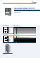
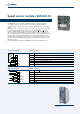
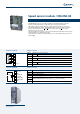
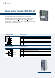
Speed sensor module / EM-ENC-04
The EM-ENC-04 speed sensor module extends the standard terminal board of the
inverter,providinganinterfaceforlinedriverspeedsensorswithZchannel.
ThismoduleisabletomanageTTL,HTL,orpush-pullincrementalspeedsensorsto
standard EIA RS422 (line driver). The EM-ENC-04 speed encoder module is equipped
with 6 control terminals for A,
A
, B, BdirectionsignalsandZand
Z
zero signals
transmitted by the speed sensor.
The same module also features a ± 10 V and ± 20 mA analog input and a ± 10 V voltage
output in addition to a digital relay output.
The module also features two output voltages (+ 5 V and + 24 V) for the speed sensor
power supply.
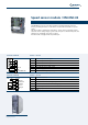
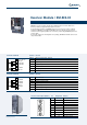
Location of EM-ENC-04 module on the
frequency inverter
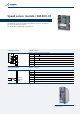
Terminal board X410A Terminal Function
X410A.1 Channel A speed sensor input
X410A.2
Channel
A speed sensor input
X410A.3
Channel B speed sensor input
X410A.4
Channel
B
speed sensor input
X410A.5
ChannelZspeedsensorinput
X410A.6
Channel
Z speed sensor input
X410A.7 + 5 V power supply output (200mA)
Terminal board X410B Terminal Function
X410B.1 + 20 V power supply output (180 mA)
X410B.2 Power supply GND
X410B.3 ± 10 V analog output
X410B.4 ± 10 V analog input
X410B.5
EM-S1OUTD multifunction relay output, U
max
= 24 V, 1 A (ohmic)
X410B.6
X410B.7 GND
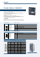
1
2
3
4
5
6
7
A
B
Z
+5V out
ENCODER LineDriver
A
Z
B
1
2
3
4
5
6
7
+20V out
GND
EM-S1OUTA
EM-S1INA
EM-S1OUTD.1
EM-S1OUTD.2
GND
±10Vref