
Technical data


43
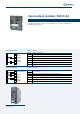
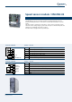
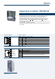
Speed sensor module / EM-ENC-02
The EM-ENC-02 speed sensor module extends the standard terminal board of the
inverter, providing an interface for line driver encoders with relative DC + 5 V power
supply.
The same module is equipped also with a DC 0 ... 20 mA and +/- 20 mA analog input
and a DC + 20 mA analog output, together with an input for a PTC thermal probe and
a digital port configurable as an input or output.
Also this module is equipped with a Systembus port.
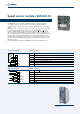
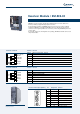
Location of EM-ENC-02 module on the
frequency inverter
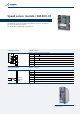
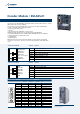
Terminal board X410A Terminal Function
X410A.1 Channel A speed sensor input
X410A.2
Channel
A speed sensor input
X410A.3
Channel B speed sensor input
X410A.4
Channel
B
speed sensor input
X410A.5
+ 5 V (200 mA) power supply output
X410A.6 5V power supply GND
X410A.7 EM-S1IND/OUTD digital input/output
Terminal board X410B Terminal Function
X410B.1 Input for motor PTC
X410B.2 GND for motor PTC
X410B.3 EM-S1OUTA 0 ... 20 mA analog output
X410B.4 EM-S1INA +/- 10 V and +/- 20 mA analog input
X410B.5 CAN-Low Systembus
X410B.6 CAN-HighSystembus
X410B.7 GND
1
2
3
4
5
6
7
A
B
+5V out
GND
EM-S1IND/OUTD
ENCODER LineDriver
A
B
PTC
GND-PTC
EM-S1OUTA
EM-S1INA
CAN-Low
CAN-High
GND
1
2
3
4
5
6
7
10Vref
PTC
θ