
Technical data


42
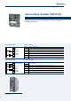
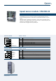
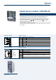
Speed sensor module / EM-ENC-01
The EM-ENC-01 expansion module extends the number of speed sensor inputs
of terminal board of the frequency inverter, and also increases the number of
configurable pulse outputs with encoder repetition output with encoder repetition
output.
EM-ENC-01isabletoacquirebothTTLandHTLincrementalspeedsensorsaccording
to standard EIA RS422 (line driver) with 5-volt logic. The EM-ENC-01 speed sensor
module is equipped with connection terminals for signals A, A, B and
B
of the line
driver speed sensor and terminals for repetition output of the same signals (speed
sensor emulation). This makes it possible to create master-slave configurations between
several separate units using output signals of one unit as input signals of the next.
The DC +/- 10 V analog input can be used for the inverter frequency reference signal.
The same terminal board also provides a DC + 5 V (200 mA) power supply for the line
driver speed sensor.
As other EM expansion modules, the EM-ENC-01 features a Systembus interface.
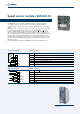
Location of EM-ENC-01 module on the
frequency inverter
Terminal board X410A Terminal Function
X410A.1 Channel A speed sensor input
X410A.2
Channel
A speed sensor input
X410A.3
Channel B speed sensor input
X410A.4
Channel
B
speed sensor input
X410A.5
+ 5 V (200 mA) power supply output
X410A.6 5 V power supply GND
X410A.7 Speed sensor channel A repetition output
Terminal board X410B Terminal Function
X410B.1
Channel
A
speed sensor repetition output
X410B.2 Channel B speed sensor repetition output
X410B.3
Channel
B speed sensor repetition output
X410B.4 EM-S1INA +/- 10 V analog input
X410B.5 CAN-Low Systembus
X410B.6 CAN-HighSystembus
X410B.7 GND
1
2
3
4
5
6
7
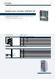
A
B
+5V out
GND
A out
ENCODER LineDriver
A
B
1
2
3
4
5
6
7
10Vref
A out
B out
B out
EM-S1INA
CAN-Low
CAN-High
GND
A
B