
Technical data


39
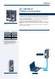
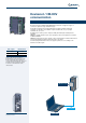
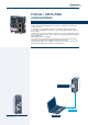
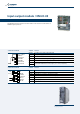
Input-output module / EM-IO-02
Like EM-IO-01, the EM-IO-02 expansion module extends the standard inputs and
outputs featured on ACT frequency inverters.
The EM-IO-02 module has a slightly modified layout compared to the -01 version,
featuring an input for a PTC thermal probe in place of one of the module relay
outputs.
The functions of all the other terminals are same as in EM-IO-01.
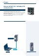
Location of EM-IO-02 module on the
frequency inverter
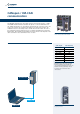
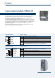
Terminal board X410A Terminal Function
X410A.1 20 V power supply output (180 mA)
X410A.2 20 V power supply GND
X410A.3
EM-S1IND multifunction digital input V
max
= 30 V (24 V/10 mA ), PLC compatible
X410A.4
EM-S2IND multifunction digital input V
max
= 30 V (24 V/10 mA ), PLC compatible
X410A.5
EM-S3IND multifunction digital input V
max
= 30 V (24 V/10 mA ), PLC compatible
X410A.6
EM-S1OUTD multifunction relay output, U
max
= 24 V, 1 A (ohmic)
X410A.7
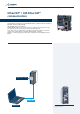
Terminal board X410B Terminal Function
X410B.1 Input for motor PTC
X410B.2 GND for motor PTC
X410B.3 EM-S1INA +/- 10 V or +/- 20 mA analog input
X410B.4 EM-S1OUTA +/- 10 V multifunction analog output
X410B.5 CAN-Low Systembus
X410B.6 CAN-HighSystembus
X410B.7 GND for +/- 10 V signals
1
2
3
4
5
6
7
+20V / 180mA
GND 20V
EM-S1IND
EM-S2IND
EM-S3IND
EM-S1OUTD
EM-S1OUTD
1
2
3
4
5
6
7
PTC
GND-PTC
EM-S1INA
EM-S1OUTA
CAN-Low
CAN-High
GND 10V
10Vref
PTC
θ