
Technical data


38
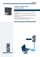
Input-output module / EM-IO-01
The EM-IO-01 expansion module extends the number of the standard inputs and
outputs provided on the ACT inverter for connection of various applications.
Analog inputs and outputs can be available also with bipolar signals and must
therefore be configured with inverter parameters.
The supplementary digital inputs provided on the expansion module are electrically
equivalent to the standard inputs. The relay changer contact represents an alternative
for the activation of high power to the relay output available as a standard feature.
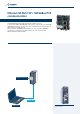
SYSTEMBUS is available on two control terminals and supports easy control of
decentralised drive systems.
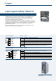
The module is equipped with a removable terminal board divided into two parts
(X410A and X410B) that are physically separated.
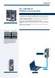
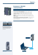
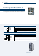
Location of EM-IO-01 module on the
frequency inverter
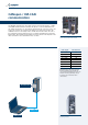
Terminal board X410A Terminal Function
X410A.1 20 VDC power supply output (180 mA)
X410A.2 20 V power supply GND
X410A.3
EM-S1IND multifunction digital input V
max
= 30 V (24 V/10 mA ), PLC compatible
X410A.4
EM-S2IND multifunction digital input V
max
= 30 V (24 V/10 mA ), PLC compatible
X410A.5
EM-S3IND multifunction digital input V
max
= 30 V (24 V/10 mA ), PLC compatible
X410A.6
EM-S1OUTD multifunction relay output, U
max
= 24 V, 1 A (ohmic)
X410A.7
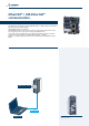
Terminal board X410B Terminal Function
X410B.1
EM-S2OUTD multifunction relay output, U
max
= 24 V, 1 A (ohmic)
X410B.2
X410B.3 EM-S1INA +/- 10 V or +/- 20 mA analog input
X410B.4 EM-S1OUTA +/- 10 V multifunction analog output
X410B.5 CAN-Low Systembus
X410B.6 CAN-HighSystembus
X410B.7 GND for +/- 10 V signals
1
2
3
4
5
6
7
+20V / 180mA
GND 20V
EM-S1IND
EM-S2IND
EM-S3IND
EM-S1OUTD
EM-S1OUTD
1
2
3
4
5
6
7
EM-S2OUTD
EM-S2OUTD
EM-S1INA
EM-S1OUTA
CAN-Low
CAN-High
GND 10V
10Vref